Maintaining cooling efficiency during air mover failure

a technology of air mover and cooling efficiency, which is applied in the direction of electrical apparatus casings/cabinets/drawers, lighting and heating apparatus, instruments, etc., can solve problems such as system malfunction or error, and each electronic device may generate heat,

Inactive Publication Date: 2003-07-01
ORACLE INT CORP
View PDF23 Cites 78 Cited by
  • Summary
  • Abstract
  • Description
  • Claims
  • Application Information

AI Technical Summary

Problems solved by technology

However, when operating, each electronic device may generate heat.
If enough heat is generated within the enclosure to cause any of the enclosed electronic devices to operate outside of their operational temperature range, problems may occur.
For example, in some cases, increased temperature may cause a system to malfunction or behave erroneously.
Sometimes, increased heat may even damage the electronic devices or components within the enclosure.
In other systems though, factors such as the size of the enclosure or the orientation of the device within the enclosure may limit the beneficial effects of convection.
One problem with systems that simply radiate heat is that the heat may accumulate inside an area in the enclosure.
For example, convection may no longer assist in cooling if all of the air in an area becomes equally heated.
The top component may quickly lose any benefits of convection due to the accumulation of heated air in the top of the enclosure.
Another situation where this might arise occurs when many devices are mounted in close proximity in an enclosure.
Each device's ability to radiate heat away from itself may be limited if the surrounding air has already been heated by the other components.

Method used


Image

  • Maintaining cooling efficiency during air mover failure
  • Maintaining cooling efficiency during air mover failure
  • Maintaining cooling efficiency during air mover failure

Examples


Embodiment Construction

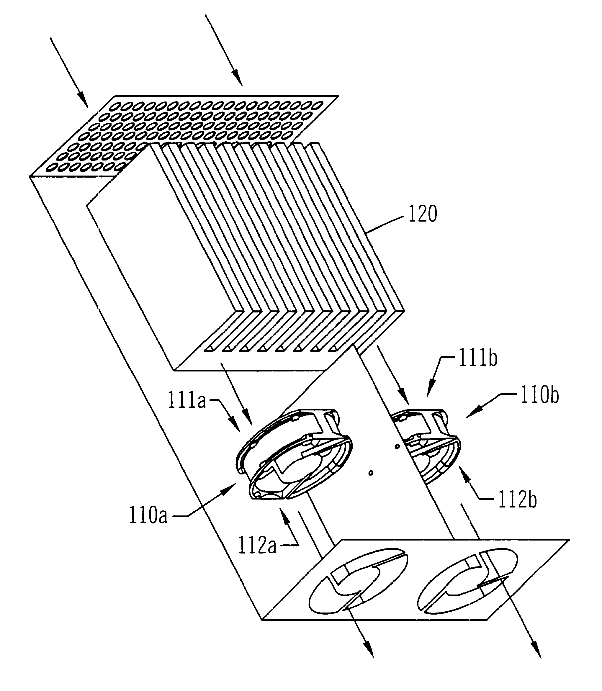
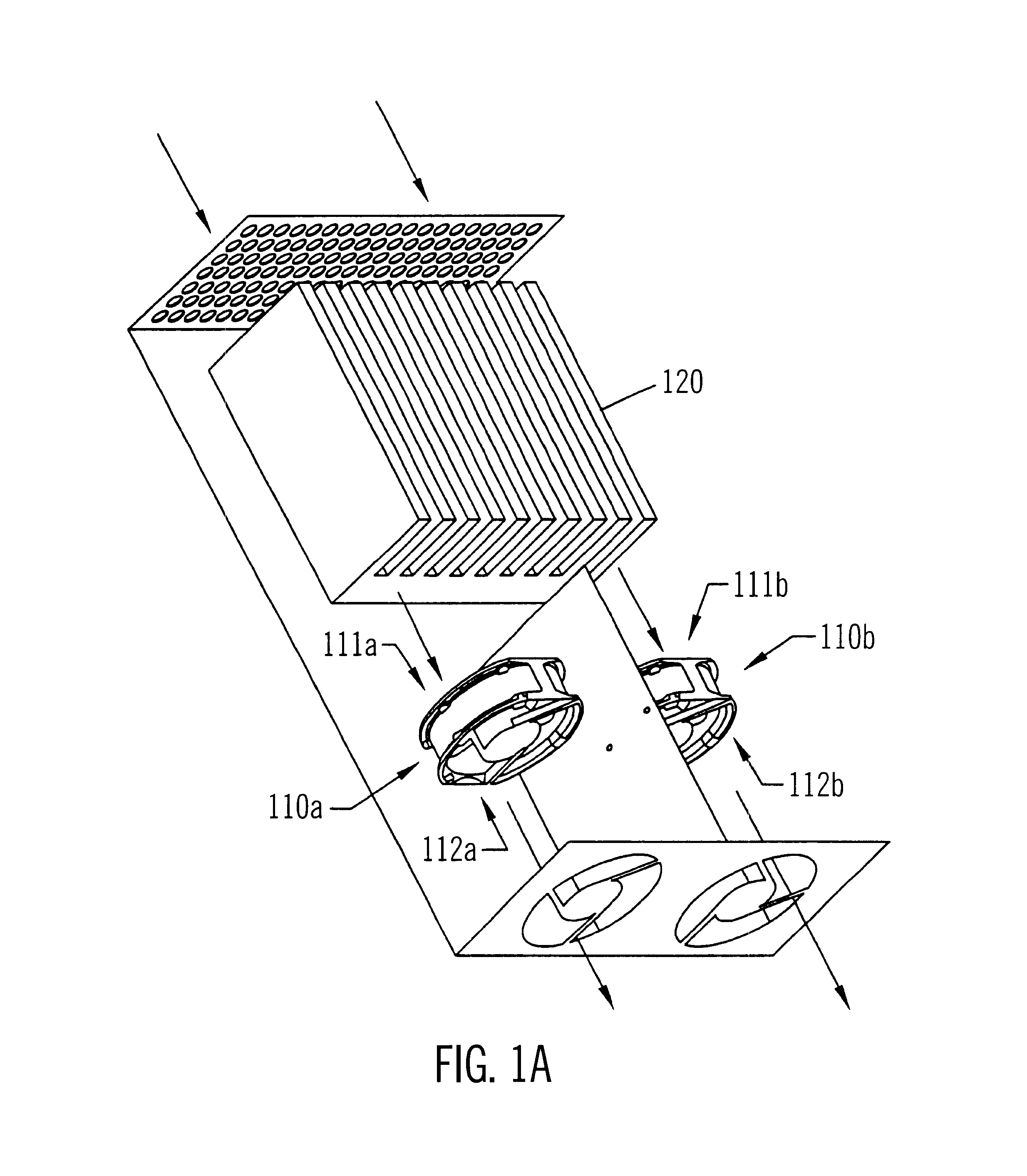
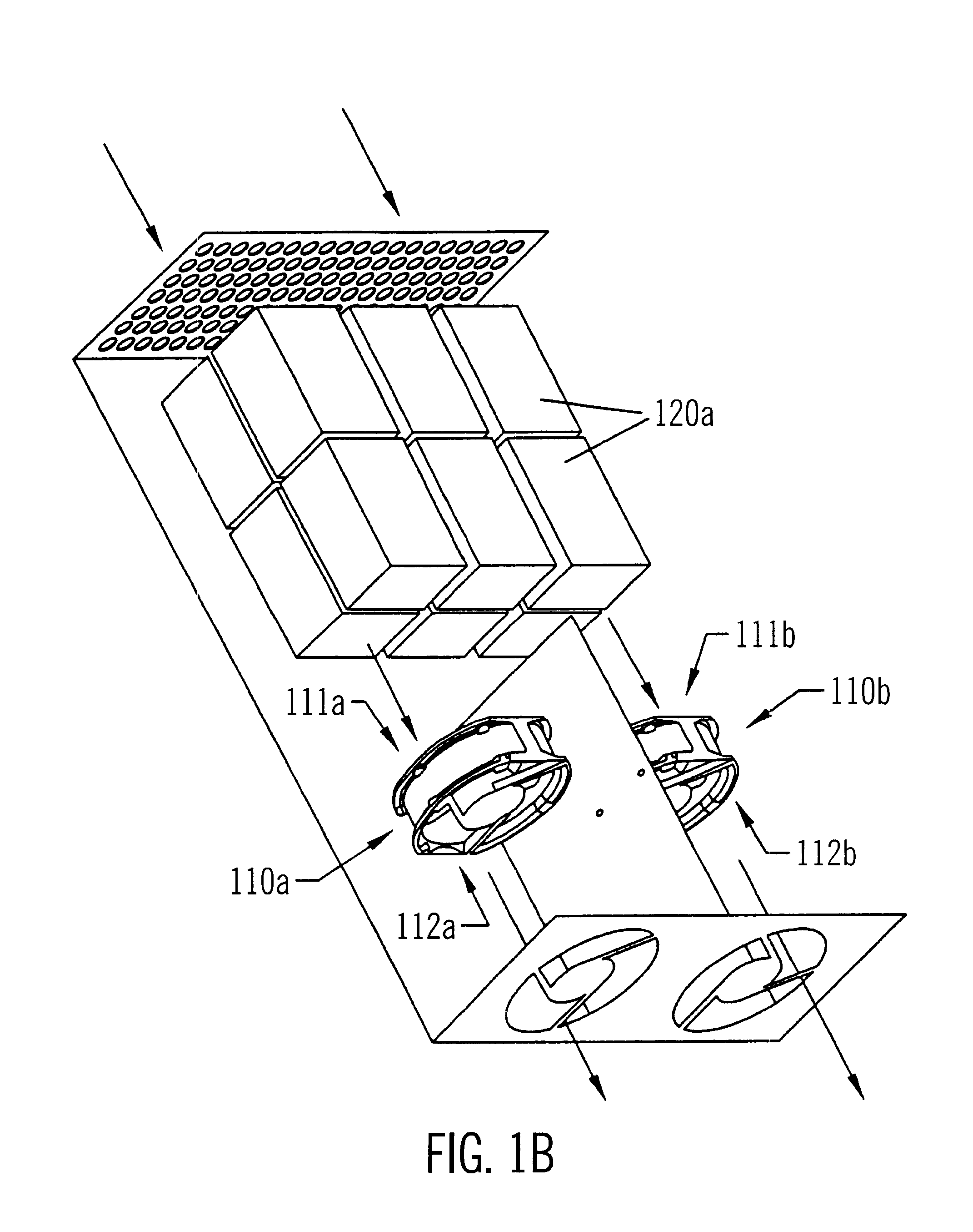
FIG. 1a shows an example of an enclosure containing several air movers 110 that are cooling a thermal load 120. In FIG. 1a, the enclosure is shown without walls to better illustrate the air movement within the enclosure. The thermal load 120 may be any heat-generating component in an electrical enclosure. For example, in one embodiment, the thermal load 120 may be a disk drive. In another embodiment, the thermal load 120 may be an arrangement of disk drives, as is shown in FIG. 1b. The disk drives may, in one embodiment, be configured as a redundant array of independent disks (RAID) system. In other embodiments, the thermal load 120 may instead or additionally include other heat-generating components such as microprocessors.

Each air mover 110 has an intake 111 and an outtake or exhaust 112. The air movers 110 circulate air by drawing the air in at the intake 111 and expelling that air through the exhaust 112 so that the air within an air channel is moved in a forward direction (as i...


PUM


Abstract

A method and apparatus may be employed for maintaining cooling efficiency during air mover failure. An electrical enclosure may include a heat-generating thermal load, multiple air movers configured to remove heat from the thermal load, and a backward-airflow reducing device configured to reduce the amount of air that can be drawn backwards through one of the air movers if that air mover fails. The backward-airflow reducing device may be a valve configured to open while the air mover if functioning and to close when the air mover is not functioning.

Description

1. Field of the InventionThis invention relates to cooling electronic enclosures and, more particularly, to the use of air movers to cool electronic enclosures.2. Description of the Related ArtElectronic enclosures may contain many different electronic devices that are designed to operate within certain temperature ranges. However, when operating, each electronic device may generate heat. If enough heat is generated within the enclosure to cause any of the enclosed electronic devices to operate outside of their operational temperature range, problems may occur. For example, in some cases, increased temperature may cause a system to malfunction or behave erroneously. Sometimes, increased heat may even damage the electronic devices or components within the enclosure.In order to reduce heat-related problems, many electronic enclosures include cooling devices. One simple example of a cooling device is a passive heat sink that radiates heat from a device into the surrounding air. A passi...

Claims


Application Information

Patent Timeline
Patent Type & Authority Patents(United States)
IPC IPC(8): H05K7/20
CPCH05K7/2019
Inventor GROUELL, WILLIAM L.CHONG, JR., FAY
Owner ORACLE INT CORP
Why Eureka
Try Eureka