
Humidifier with swingable cover

a technology of evaporator and cover, which is applied in the field of humidifiers, can solve the problems of difficult and time-consuming access to evaporator pads and water distribution troughs, and the condition is not always achieved, and achieves the effects of convenient and convenient use, simple construction, and economical manufactur

Inactive Publication Date: 2003-07-08
GENERAL FILTERS
View PDF15 Cites 37 Cited by
  • Summary
  • Abstract
  • Description
  • Claims
  • Application Information

AI Technical Summary

Benefits of technology

The use of the swingable cover has many advantages in that it permits easy access to the evaporator pad even if the cover is obstructed. Also, the cover may be closed due to the snap action mechanism provided on the top end of the cover which is engageable with the retaining elements provided on the cabinet. In addition, only 1 / 4 or 90.degree. turn of the solenoid valve is required to remove it from the cabinet so that the valve may be serviced or repaired. Further, the cabinet may be opened by swinging the cover about the bearing means without removing the wires to which the valve is attached or removing the water line. In addition, no tools or fasteners are required to install or to remove the bypass cover from the opening in the cabinet.
Another feature of the present invention is to provide a humidifier of the aforementioned type which is simple in construction, is economical to manufacture and is efficient in operation.

Problems solved by technology

The humidifier should be mounted in a perfectly level position although such a condition is not always achieved in practice.
With such prior art humidifiers, it is difficult and time consuming to access the evaporator pads and the water distribution troughs.

Method used


Image

  • Humidifier with swingable cover
  • Humidifier with swingable cover
  • Humidifier with swingable cover

Examples


Embodiment Construction

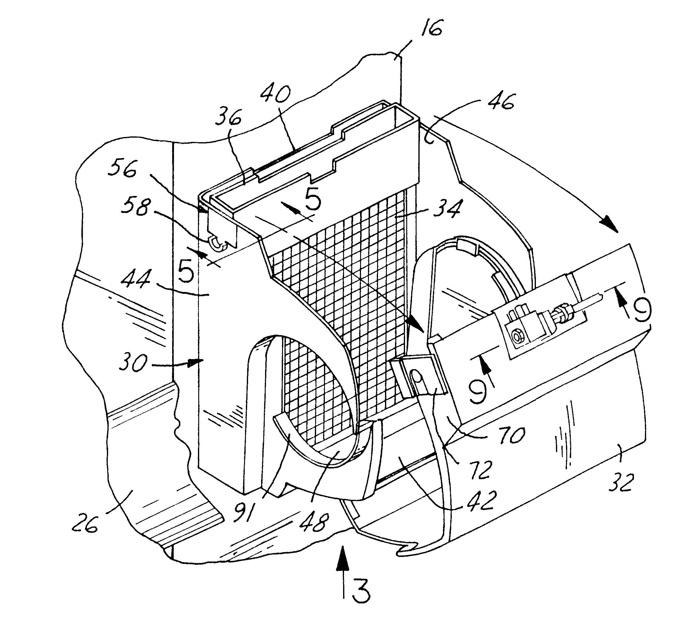
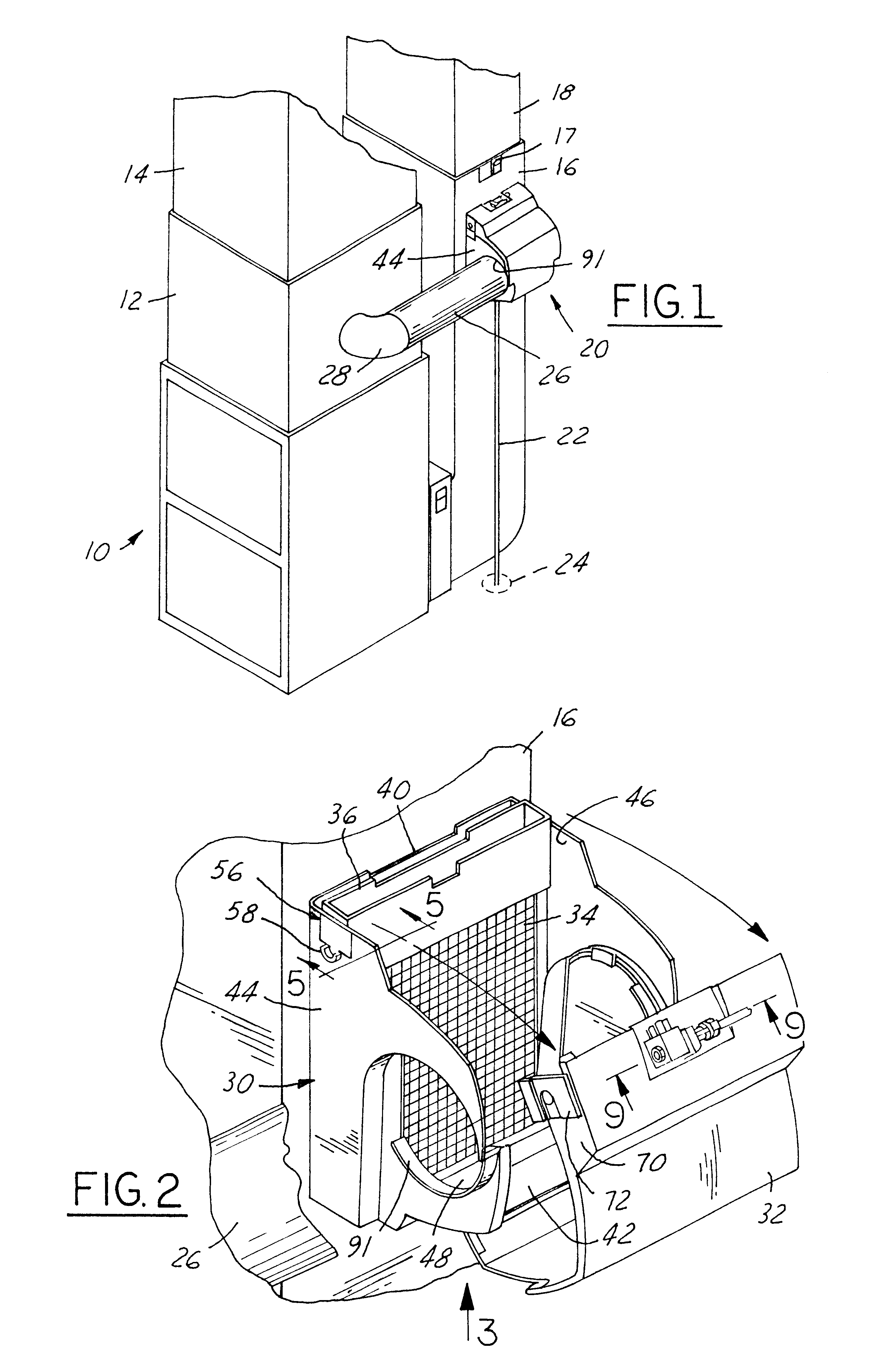
FIG. 1 shows an air treating apparatus or furnace 10 such as a forced air furnace having the usual warm air plenum 12 and warm air duct 14 and a return air plenum 16 with a return air duct 18. The flow through bypass humidifier 20 to which the present invention is directed may be mounted on either the warm air plenum 12 or, as shown in FIG. 1, on the return air plenum with equal efficiency. The humidifier 20 includes a drain sump which is connected by a line 22 to the drain 24 provided in the floor. A bypass pipe 26 connects the flow through humidifier 20 from an elbow 28 which directs the air from the warm air plenum 12 into the humidifier. The operating principal of the humidifier is based on the most efficient and economical means of evaporating water to the air. The humidifier 20 uses only five watts of electrical power during operation. The heat necessary for evaporating the waters is produced by the furnace 10.

The humidifier 20 comprises a unitary housing or cabinet 30, a swin...


PUM

PropertyMeasurementUnit
electrical poweraaaaaaaaaa
temperatureaaaaaaaaaa
areaaaaaaaaaaa

Abstract

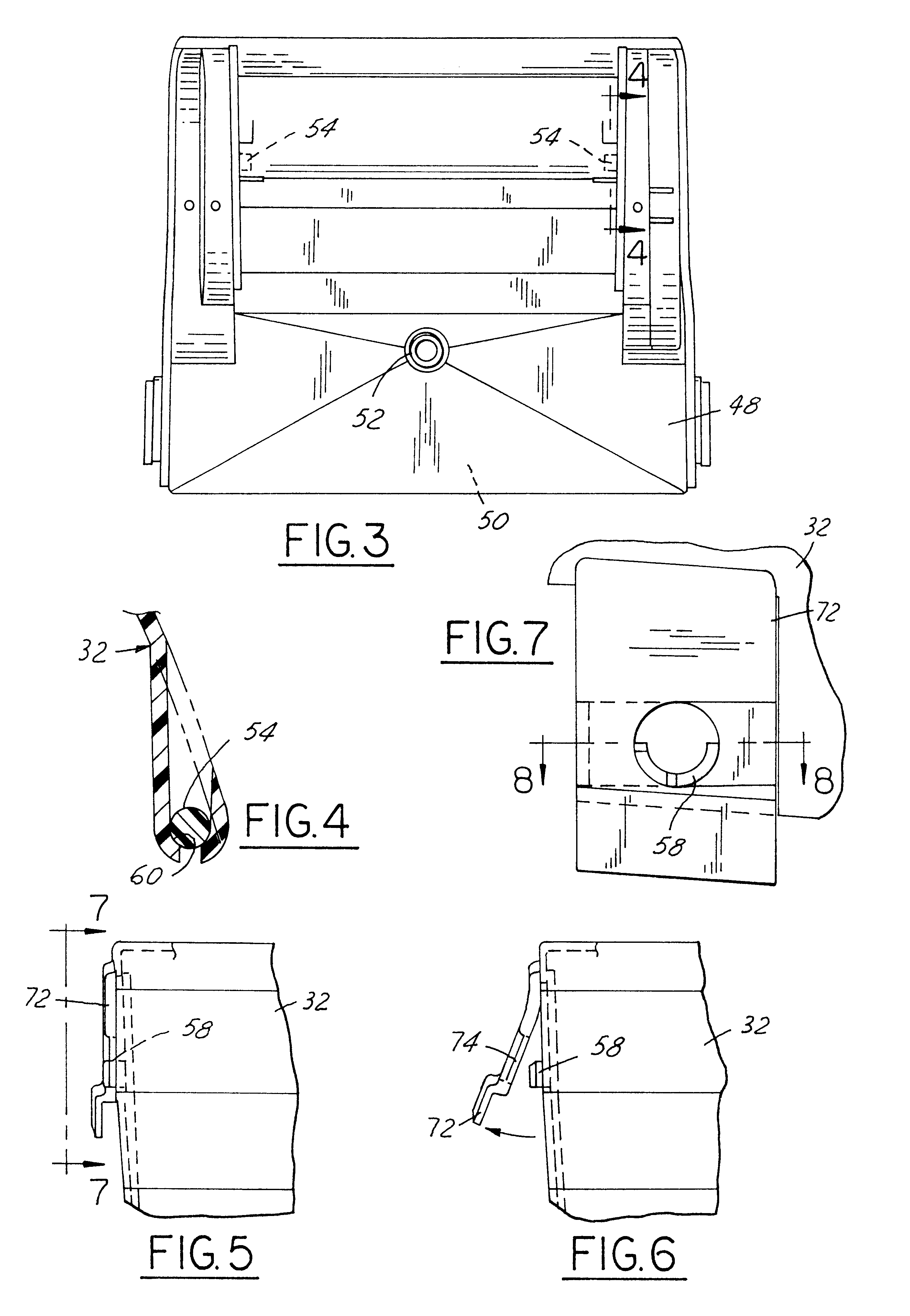
The humidifier includes a cabinet having a rear wall, a front wall, a pair of side walls, a bottom wall and a sump defined in part by the walls at the bottom of the cabinet. The cabinet has in the interior thereof means providing communication with an air system. Retainer ears are provided on the outer surfaces of the side walls near the top thereof. An evaporator pad is mounted in the cabinet adjacent and parallel to the rear wall. A water distribution trough is disposed in the interior of the cabinet adjacent the rear wall and is located above the evaporator pad for providing a substantially uniformly distributed flow of water to the evaporator pad. A pair of mounting elements are provided on the inner surfaces of the side walls near the bottom thereof. A swingable cover is provided for opening and closing the cabinet and has a top end and a bottom end. The cover at the bottom end is provided with a pair of bearing portions which are engageable with and pivotally mounted on the mounting elements. Fastening means are secured to the sides of the top end of the cover and are engageable with the retainer ears when the cabinet is closed. The cover when the fastening means are disengaged from the retainer ears being swingable relative to the mounting elements for opening the cover to permit access to the evaporator pad and to the interior of the cabinet.

Description

1. Field of the InventionThe humidifier is for use with an air system and is especially adapted for installation on a forced air furnace.2. Description of the Prior ArtThe effective distribution of water to the evaporator pad of a humidifier is an important consideration in the design of the humidifier. It is highly desirable that the water be uniformly disbursed over the entire pad area. It is also desirable that the distribution of the water remain uniform despite slight errors in the mounting of the humidifier. The humidifier should be mounted in a perfectly level position although such a condition is not always achieved in practice. The water distribution means must be capable of providing substantially uniform distribution of the water to the evaporator pad even though the humidifier is not perfectly level.Humidifiers for use with an air system such as a forced air furnace is shown in several expired patents assigned to the assignee of record including the Engel, U.S. Pat. No. ...

Claims


Application Information

Patent Timeline
Patent Type & Authority Patents(United States)
IPC IPC(8): F23L13/00
CPCF23L13/00Y10S261/15
Inventor REDNER, CARL R.LUTTY, JR., RICHARD J.
Owner GENERAL FILTERS
Learn More