Method and apparatus for flow cytometry

a flow cytometry and apparatus technology, applied in the field of flow cytometry, can solve the problems of inability to accurately the method did not actually determine the drop delay time, and the detection of sensitive equipment was difficult to achieve. achieve the effect of accurately determining the drop delay tim

Inactive Publication Date: 2003-07-08
BECKMAN COULTER INC
View PDF108 Cites 240 Cited by
  • Summary
  • Abstract
  • Description
  • Claims
  • Application Information

AI Technical Summary

Benefits of technology

The present invention provides a novel method of compensating for changes in a flow cytometer and accurately determining a drop delay time for a particular particle in the stream. A detected droplet can be charged based on a drop delay time that is computed based on a measurement of the speed of the fluid in the stream. Therefore, knowledge of the droplet charging location and the speed characteristics of the stream allows the cytometer to more accurately charge the droplet containing the particle at the droplet charging location.

Problems solved by technology

Prior work in the field of flow cytometry apparently has been unsuccessful in solving these problems.
However, this method did not actually determine a drop delay time for a particle detected in the stream.
Furthermore, it required very sensitive equipment to detect the change in the undulation of the surface and has apparently since the patent issued in 1987 never been made to work in a commercial product.
Therefore, equilibration of the cytometer was still likely a one and a half hour procedure if this method were used.
However, it did not appreciate the ability of a monitoring system to determine a wealth of other characteristics of a stream and thereby automatically provide feedback to the flow cytometer.

Method used


Image

  • Method and apparatus for flow cytometry
  • Method and apparatus for flow cytometry
  • Method and apparatus for flow cytometry

Examples


Embodiment Construction

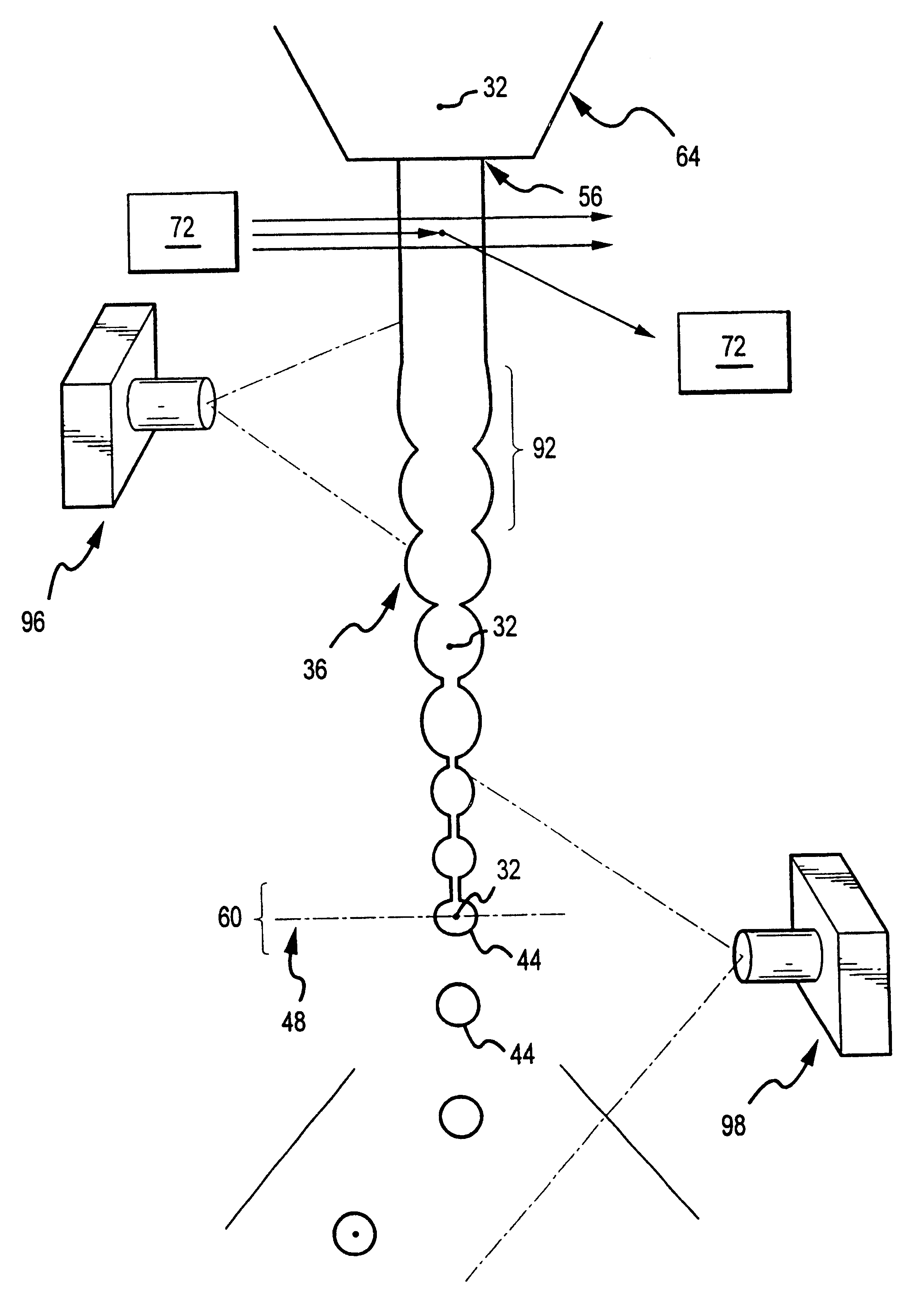
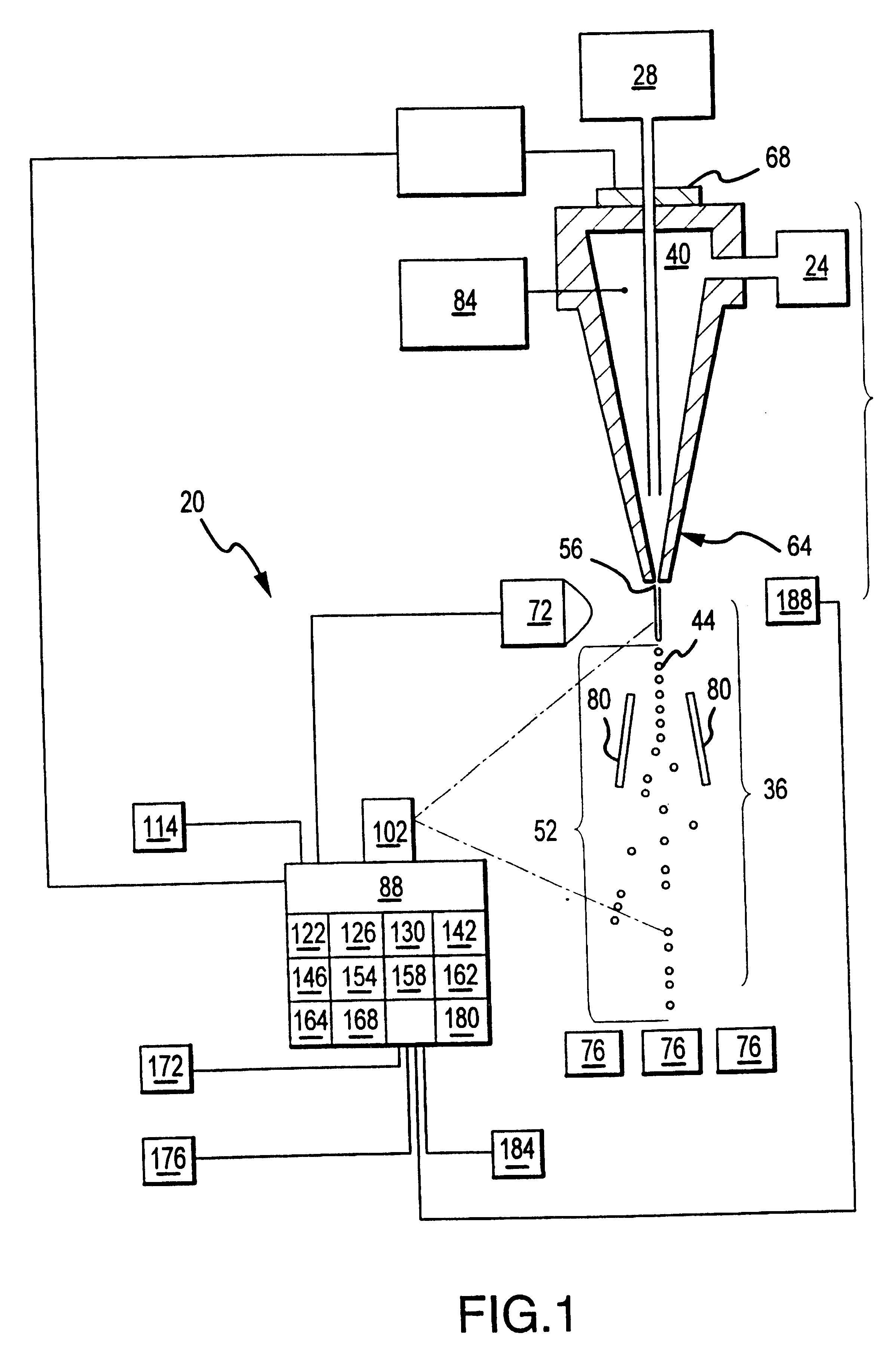
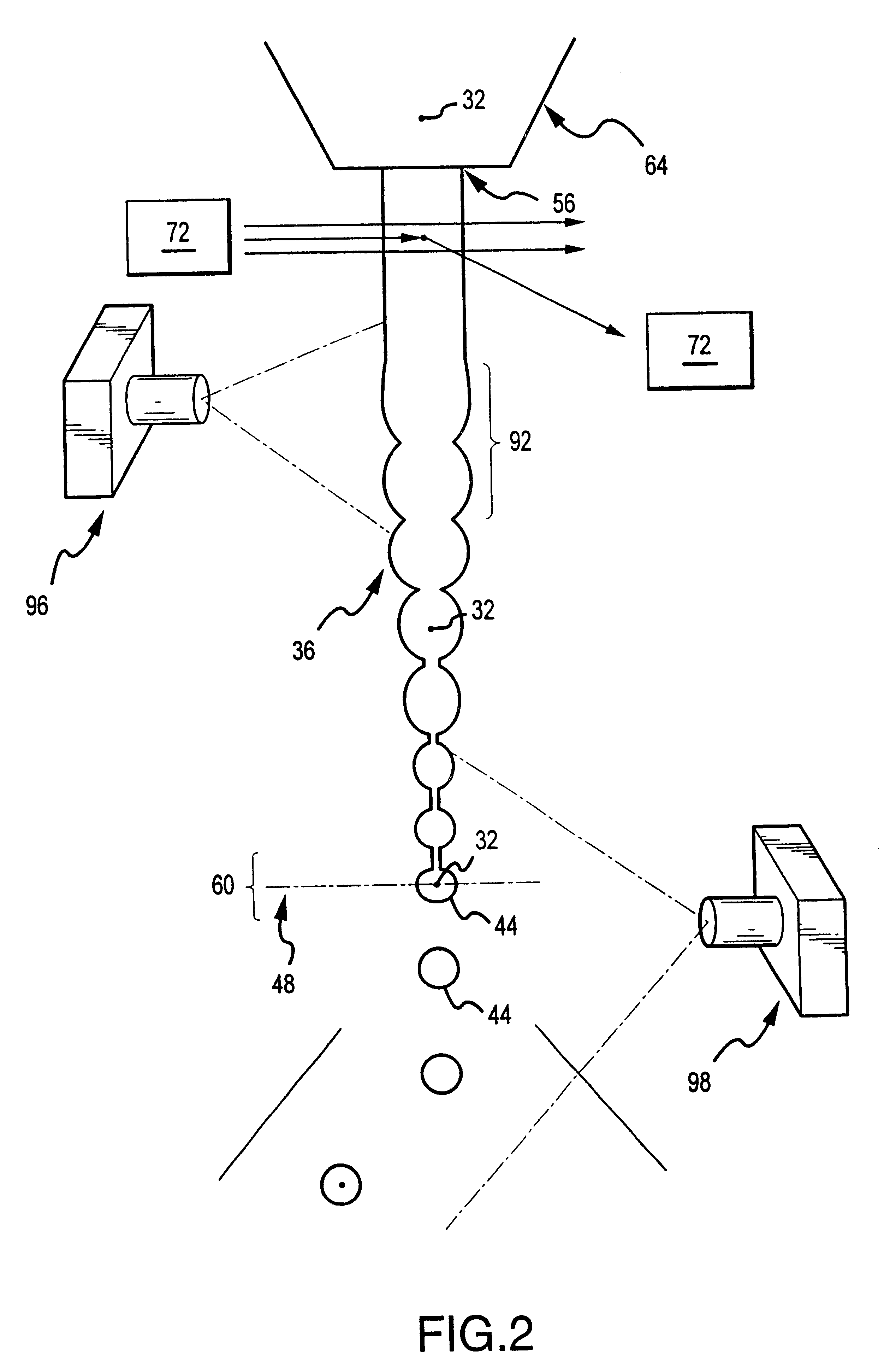
Referring now to FIG. 1, a preferred embodiment of the invention can be seen in detail. The flow cytometer (20) can utilize a source of stream fluid (24) to supply stream fluid to establish a sheath of fluid in which particles (32) can be suspended. The source of particles (28) can insert the particles from time to time such that the particles become suspended in the stream fluid and are hydrodynamically focused in the stream. A stream (36) comprised of the stream fluid (40) and the particles (32) can then be established below the nozzle (64) of the flow cytometer. The stream can be established in a steady state condition such that droplets (44) are formed and break away from a contiguous part of the stream. When the stream is established in this steady state fashion, a stable break-off point (48) can be established. This stream can be strobed with a stroboscope to illuminate the stable stream. At the break-off point the stream breaks off into droplets with these droplets centered a...


PUM

PropertyMeasurementUnit
setup timeaaaaaaaaaa
drop delay timeaaaaaaaaaa
timeaaaaaaaaaa

Abstract

A flow cytometer (20) capable of utilizing an imaging system including a sensor (88) to determine various properties of the flow cytometer (20). Importantly, the imaging allows for determination of a drop delay time (154). Other characteristics that can be determined include at least the width of the stream, pressure of the stream, effect of charged droplets on other droplets (44), trajectory of the stream, resonant frequency, wavelengths, change in position of droplet break-off point (150), and others. An automatic warning system (180) can be used to alert an operator of an anomaly during setup or during normal operation. Furthermore, a mechanical interrupter can be used to shield a sort result from contamination by an incorrectly functioning stream. The cytometer (20) also allows for the disablement of the sort, particularly the charging and deflection systems. In addition, a more accurate system for detecting the speed of the stream can be used. The imaging system including a sensor (88) can allow for the removal of background noise and the monitoring of a change in a stream characteristic.

Description

I. TECHNICAL FIELDThis invention relates to a method and apparatus for the analyzation and sorting of particles, e.g., in a flow cytometer. In the field of flow cytometry it is common to establish a stream of sheath fluid with a stream of particles suspended in that sheath fluid. This stream can then be perturbed such that droplets form and the particles are contained in the droplets as they break-off from the end of a contiguous stream. The droplets can then be sorted as desired by detecting desired particles and establishing a charge on an individual droplet just before it breaks away from the contiguous part of the stream. The droplet containing the desired particle can then be deflected with an electric field into a collection container. As part of this process, it is optimal to know when a droplet containing a desired particle reaches the charging location such that that particular droplet can be charged while droplets charging as few neighboring droplets as necessary. This all...

Claims


Application Information

Patent Timeline
Patent Type & Authority Patents(United States)
IPC IPC(8): G01N15/14G01N33/48
CPCG01N15/1404G01N15/1427G01N2015/1406G01N2015/1443G01N2015/149
Inventor MALACHOWSKI, GEORGE C.
Owner BECKMAN COULTER INC
Why Eureka
Try Eureka