Add-on housing

a mounting housing and mounting bracket technology, applied in the direction of electrical apparatus, electrical apparatus, casings/cabinets/drawers, etc., can solve the problems of preventing the removal of the cover, unable to attach the mounting housing, and generally not being able to use special tools to remove the cover, etc., to achieve the effect of convenient pre-assembling

Inactive Publication Date: 2003-07-15
CONTACT
View PDF13 Cites 17 Cited by
  • Summary
  • Abstract
  • Description
  • Claims
  • Application Information

AI Technical Summary

Benefits of technology

It is the object of the present invention to provide a mounting housing for the mentioned components to be guided by means of a mounting housing, which can readily be pre-assembled, permits a convenient access to the inner space of the mounting housing at any time, and which enables a tight sealing of the access opening to the inner space of the mounting housing, or its clearing, respectively, without special tools. Moreover, the invention is to provide a mounting housing which in the pre-assembled condition can be attached at a corresponding mounting surface.
In order to improve the secureness of the cover the housing body comprises a contact area for the extended area of the cover, with these areas being preferably formed in a positive manner. This positive fit between the extended area and the contact area improves the clamping effect of the retaining means in the secured condition of the cover.
In addition, the extended area of the cover may comprise a, contoured area which, for example, may be provided with recesses (longitudinal grooves, transverse grooves) formed in the cover. If the extended area is elastically deformable at least in the contoured area, the extended area additionally serves as a vibration protection for the cover.
In order to tightly seal the access opening in the closed condition of the cover a sealing element (e.g. an O-ring) is, arranged in the area of the access opening. If the sealing element is elastic so that it is elastically deformable with the cover in the closed and secured condition due to an active connection with same, the forces which are thereby generated and act on the cover contribute to the secureness of the cover.
In an embodiment, the cover is movably hooked in the housing body by means of structures (e.g. projections forming a hinge) formed at the cover and the housing body, preferably at its first end. This construction permits a simple manufacture of the mounting housing, with the additional possibility, for example for pre-assembling the mounting housing, to remove the cover from the housing body (unhook it). This movable connection can also be made by means of shafts and / or pins which are in active connection with the cover and the housing body whereby, on the one hand, a removal of cover becomes more difficult but, on the other hand, the stability of its connection with the housing body is improved.

Problems solved by technology

This approach impedes the removal of the cover if, for example, an access is required to the feed-through of the, mounting housing for maintenance work.
In this case, the removal of a cover is generally not possible without special tools.
In addition, it is generally not possible to attach a mounting housing e.g. to a switchgear cabinet before the mounting housing has been pre-assembled with corresponding electrical and / or optical conductors and / or connectors.
Similar problems result if mounting housings are used for (flexible) fluid lines, mechanical components such as e.g. articulated shafts or Bowden cables and the like, for guiding same (in an angled fashion) out of the housing of a corresponding device.

Method used


Image

  • Add-on housing
  • Add-on housing
  • Add-on housing

Examples


Embodiment Construction

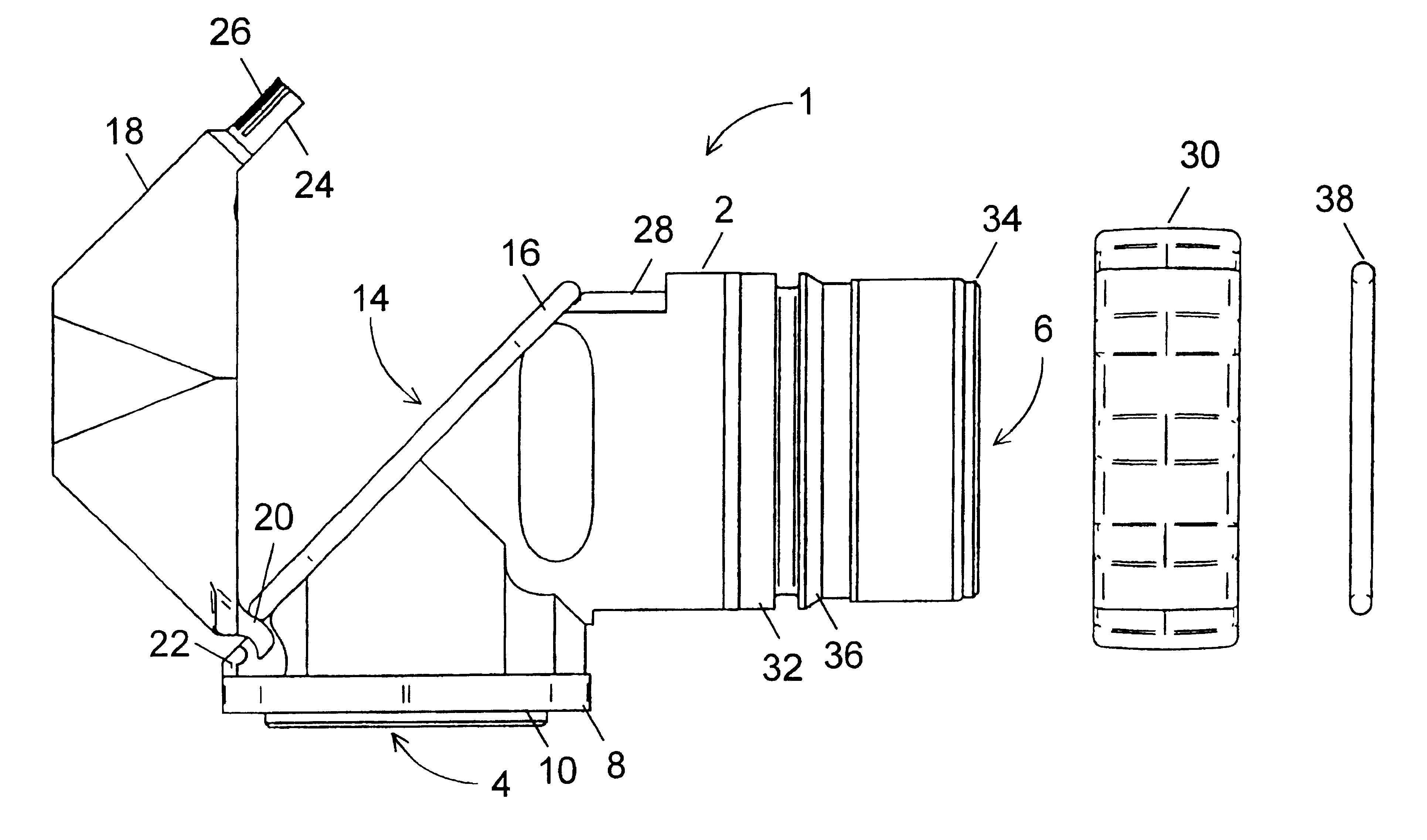
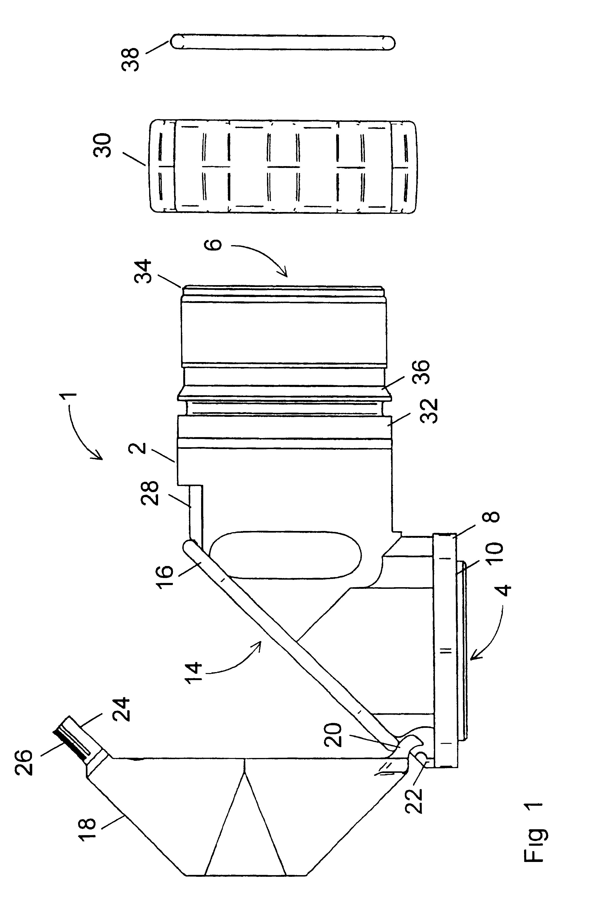
The mounting housing 1 shown in FIGS. 1 to 6 comprises a housing body 2 angled by 90.degree., through which a conductor feed-through (not identified) extends between openings 4 and 6. The conductor feed-through has an essentially round cross-section and serves to accommodate conductors for electrical and / or optical signals. As mentioned, the mounting housing 1 can also be used for the accommodation of other lines and components, such as e.g. fluid lines, Bowden cables, and articulated shafts.

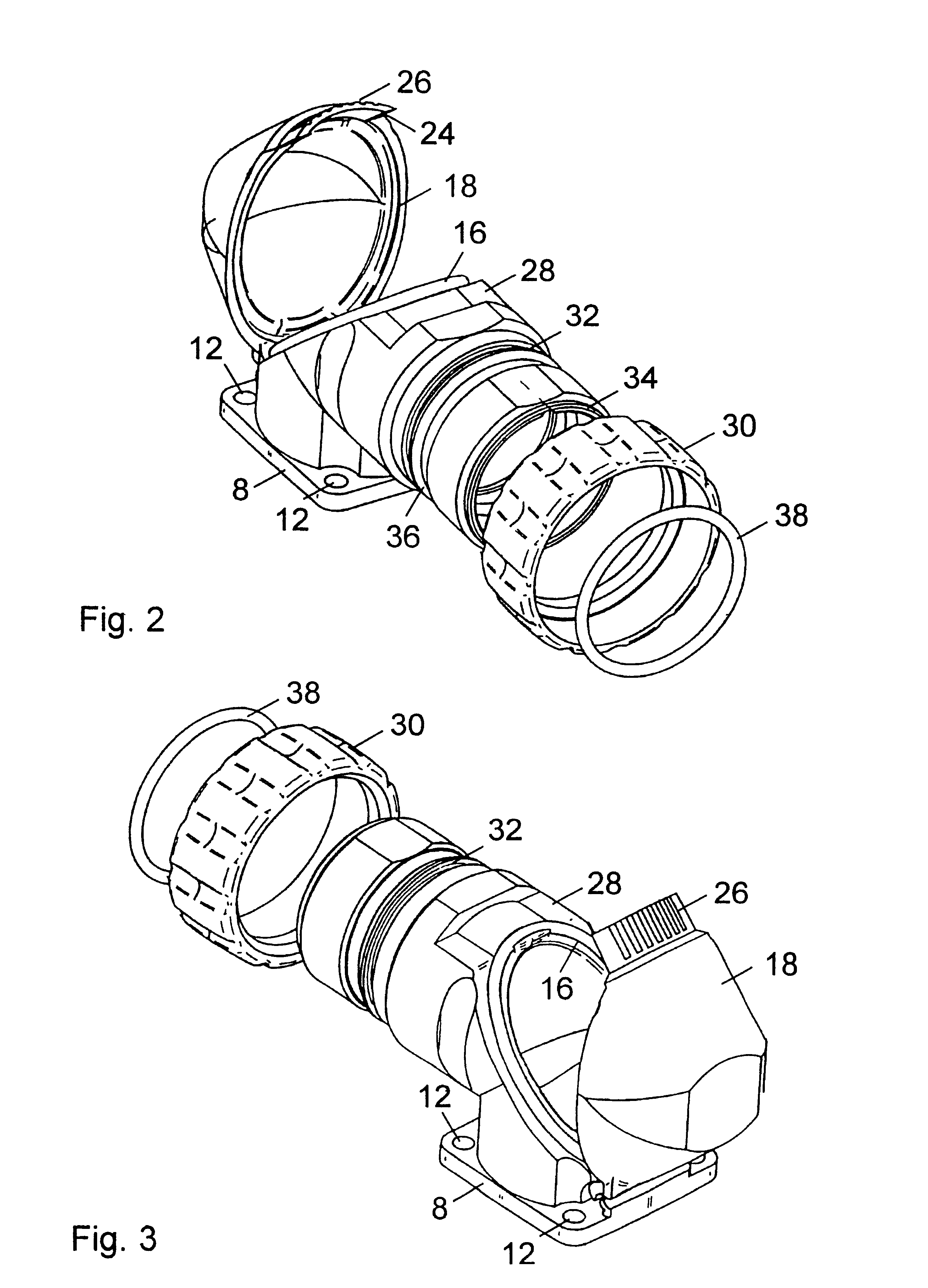
At its end in the area of the opening 4 the housing body 2 comprises a mounting flange 8 and a shoulder 10 formed thereon. As can be seen in FIG. 5, the mounting flange 8 has an essentially rectangular cross-section and comprises one hole 12 each in its corner areas. The mounting flange 8 and its holes 12 serve to secure the mounting housing 1 on a surface, e.g. of an electrical switchgear cabinet. In the area of the opening 4 the shoulder 10 has a cross-section which essentially corresponds to ...


PUM


Abstract

The present invention relates to a mounting housing for example or circular connectors. For a convenient pre-assembly of the mounting housing it includes an access opening which can be closed by a cover. The cover is hooked in a housing body of the mounting housing on one side and is secured at the housing body via a retaining nut, with the cover in conjunction with a seal arranged in the area of the access opening sealing same. In addition, a vibration protection is provided in that the cover includes a contoured area which in the screwed on condition is urged by the retaining nut against a corresponding area of the housing body. The mounting housing also includes a mounting flange which is formed at the housing body in such a manner that an installation and removal of the mounting housing at corresponding mounting surfaces is possible after the pre-assembly of the mounting housing.

Description

The present invention relates to a mounting housing for electrical and / or optical conductors, fluid lines, and mechanical components, such as e.g. articulated shafts or Bowden cables. The invention relates in particular to an angled mounting housing which, in the pre-assembled condition, can be attached at a corresponding mounting surface, with a cover which can easily be locked with the body of the mounting housing being used for the access to the feed-through of same.In order to attach for example connectors for electrical and / or optical conductors at a casing of a switchgear cabinet, so-called mounting housings are used. The mounting housings are attached at an external surface of the switchgear cabinet casing and comprise a feed-through which is communicating with the interior of the switchgear cabinet. The feed-through serves to guide electrical and / or optical conductors from the switchgear cabinet to a connector which is installed at the mounting housing. Mounting housings are...

Claims


Application Information

Patent Timeline
Patent Type & Authority Patents(United States)
IPC IPC(8): F16L45/00
CPCF16L45/00
Inventor HULSMANN, INGRIDANDRA, FRANK
Owner CONTACT
Why Eureka
Try Eureka