Magnet and adapter assembly for mounting on a shaft end of an electric drive

a technology of adapter and magnet, which is applied in the direction of electronic circuit testing, dynamo-electric machines, instruments, etc., can solve the problem of requiring a relatively large installation space for the adapter, and achieve the effect of pre-assembling very easily

Inactive Publication Date: 2019-07-16
BUHLER MOTOR GMBH
View PDF20 Cites 0 Cited by
  • Summary
  • Abstract
  • Description
  • Claims
  • Application Information

AI Technical Summary

Benefits of technology

[0007]The task of the invention is to devise a magnet sensor assembly which allows as simple a connection as possible to be established between a magnet sensor and a shaft end of a shaft or an inner ring of a rolling element bearing secured to the shaft, for which simple manufacturing and mounting methods may be used which are reliable and for which a large body of experiential knowledge is available. In addition, the magnet sensor assembly should be resistant to harsh environmental conditions, including chemical resistance, vibratory strength, and large fluctuations in temperature.
[0008]Since the magnet sensor assembly consists of a magnet sensor and an adapter, the respective preferences of the materials used can be utilized. By using a plastic-bonded magnet sensor, simple connection techniques and good design possibilities can be realized. By means of a force-fit mounting of the adapter on the shaft end or inner ring, simple, proven joining methods can be used.
[0009]Particularly preferred is the use of sintering material for the adapter, because this provides a plurality of design possibilities, which can be used economically. From sintering materials can be produced very precise work pieces, which is why they are very well suited for force-fit connections. In the selection of the sintering material, non-magnetic material may be preferred in order to contribute to a high degree of efficiency of the sensor magnetic circuit.
[0011]A second possibility consists in providing the adapter with at least one pin-like protrusion, which is pressed into a cavity in an axial end face of the shaft. In this case, installation space is generally saved, but a somewhat more elaborately designed shaft is required in return. The pin-like protrusion can have a polygonal, in particular hexagonal, or polygon-like cross section. In this way, the tolerances for the press-fit connection can be designed more economically.
[0014]Furthermore, a form fit between the magnet sensor and the adapter can be established easily. This is in particular achieved by the magnetic material of the magnet sensor filling the receptacle itself and a recess in a wall of the receptacle. The magnetic material in the recess is used in this case as an anti-rotation element if the recess is arranged eccentrically or does not have a round cross section. It is however also possible to provide two or more recesses, which are filled by the magnetic material of the magnet sensor.
[0017]The magnet sensor device can basically be pre-assembled very easily.

Problems solved by technology

In this case, the adapter requires a relatively large installation space, because a certain minimum material thickness is also required for strength reasons.

Method used


Image

  • Magnet and adapter assembly for mounting on a shaft end of an electric drive
  • Magnet and adapter assembly for mounting on a shaft end of an electric drive
  • Magnet and adapter assembly for mounting on a shaft end of an electric drive

Examples


first embodiment

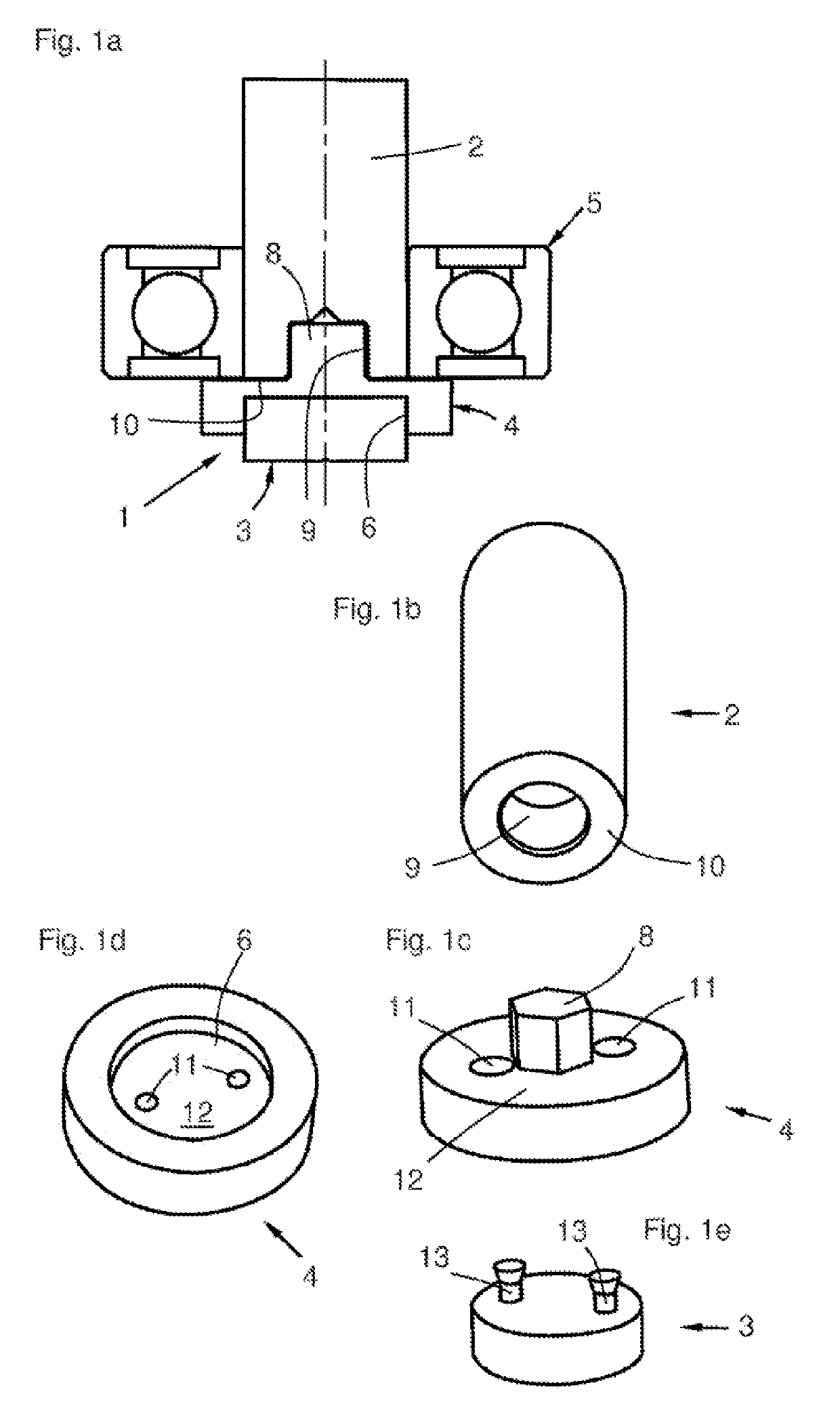
[0036]FIG. 1a shows the magnet sensor assembly 1, which is mounted on a shaft end of a shaft 2. The magnet sensor assembly 1 consists of a magnet sensor 3 and an adapter 4. Further illustrated is a ball bearing 5, with which the shaft 2 is mounted in a drive housing not shown here. In this embodiment, the adapter 4 is provided with a receptacle 6 for the magnet sensor 3, which receptacle is designed to be substantially cylindrical. In the example shown, the magnet sensor is only partially sunk into the receptacle 6. The adapter 4 includes a pin-shaped protrusion 8, which is pressed axially into a cavity 9 in the shaft end of the shaft 2 having an end face 10.

[0037]FIG. 1b shows a three-dimensional illustration of the shaft 2, with the cavity 9, which is designed as a cylindrical blind hole in the end face 10 of shaft 2.

[0038]FIG. 1c shows the disc-shaped adapter 4, with the pin 8, and a wall 12, in which two recesses 11 are also formed. The pin 8 has a slightly larger diameter than ...

second embodiment

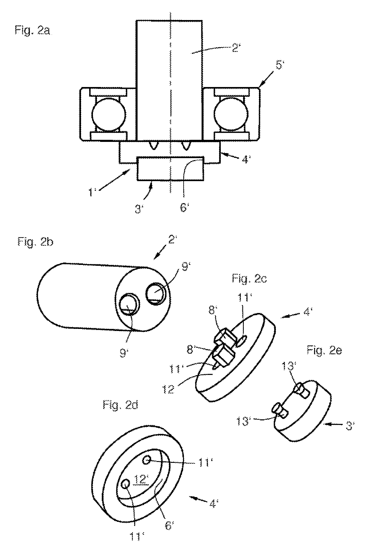
[0042]FIG. 2a shows the magnet sensor assembly 1′, with a magnet sensor 3′, an adapter 4′, a bearing 5′, and a shaft 2′. The magnet sensor 3′ is accommodated in a receptacle 6′ of the adapter and connected to the latter in a form-fit manner (not visible here) using a process similar to that discussed above.

[0043]FIG. 2b shows a second embodiment of the shaft 2′, which comprises two cavities 9′, which extend parallel to each other and to the longitudinal axis of the shaft 2′ into the shaft 2′.

[0044]FIG. 2c shows a second embodiment of the adapter 4′, with two pin-like protrusions 8′ and two recesses 11′, which are expanded conically and are apertures through a wall 12′. The length of the protrusions 8′ is slightly less than the depth of the cavities 9′ of the shaft 2′ (FIG. 2b).

[0045]FIG. 2d shows the adapter 4′ alternatively from another perspective, with a receptacle 6′ for the magnet sensor, the wall 12′, and the recesses 11′, which have a smaller cross section here than on the op...

third embodiment

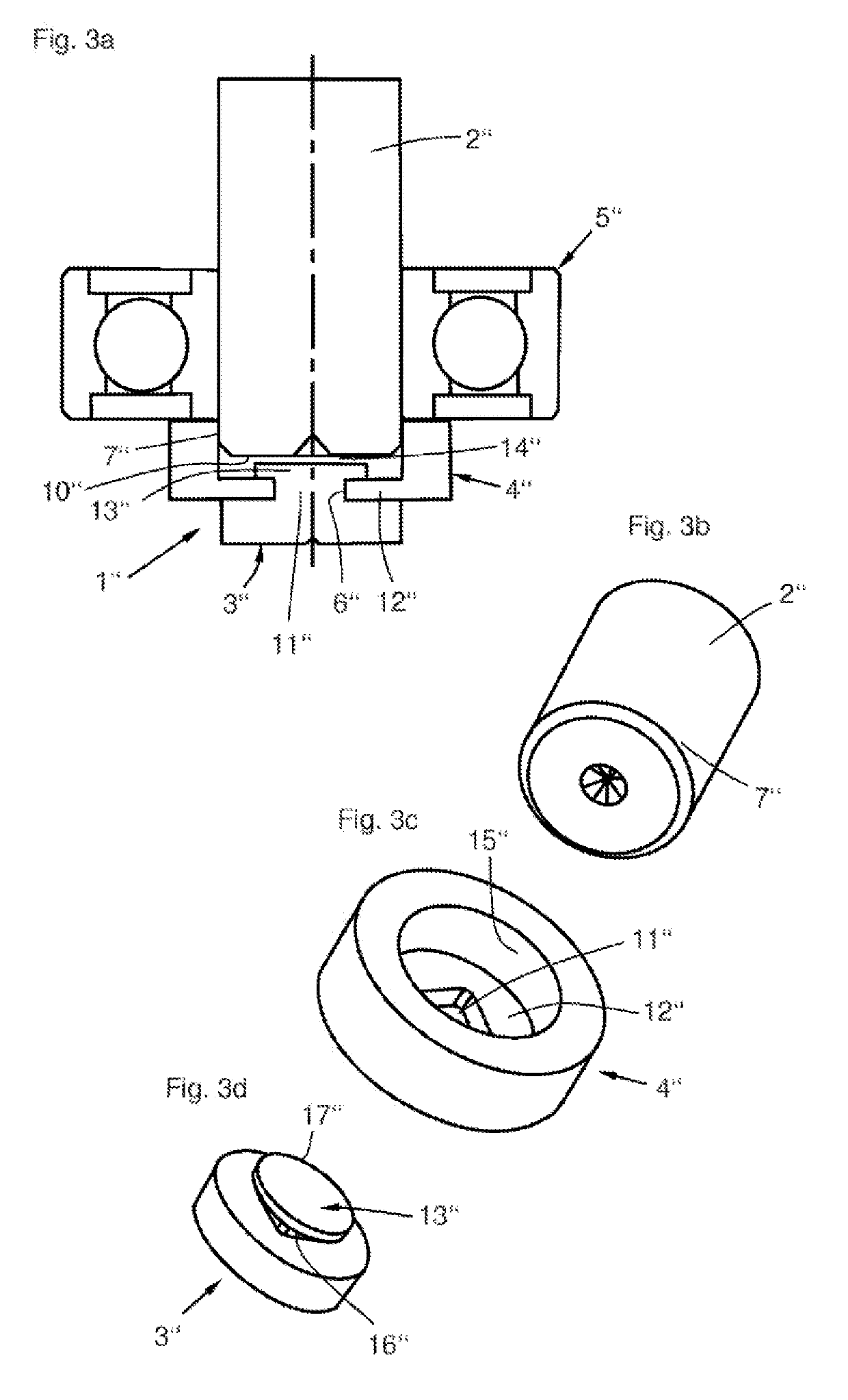
[0047]FIG. 3a shows the magnet sensor means 1″, with a shaft 2″, an adapter 4″, a magnet sensor 3″, and a ball bearing 5″. In this case, the adapter is pressed onto a section of an outer circumferential region 7″ of the shaft 2″ and is designed to be pot-shaped in its basic form, wherein a recess 11″ exists in the pot-shaped bottom, which recess also forms a receptacle 6″ for the magnet sensor. The largest portion of the magnet sensor 3″ is however free. From this exposed region of the magnet sensor 3″, a protrusion 13″ extends axially, which has an expansion at its end in order to establish a form fit with a wall 12″ of the adapter 4″. Between an end face 10″ of the shaft and the magnet sensor 3″ is provided a distance 14″, which improves the degree of efficiency of the sensor magnetic circuit.

[0048]FIG. 3b shows a third embodiment of the shaft 2″, which does not have any special receptacle geometries for the adapter, which is merely pressed onto the outer circumferential region 7″...


PUM

PropertyMeasurementUnit
magneticaaaaaaaaaa
chemical resistanceaaaaaaaaaa
vibratory strengthaaaaaaaaaa

Abstract

A magnet assembly in an electric drive having a shaft. The assembly includes a permanent magnet bonded in plastic and having two protrusions. An adapter has two protrusions and two recesses. The end face of the shaft has two cavities, which receive the two adapter protrusions to mount the adapter to the shaft. The two protrusions of the magnet are received in the recesses in the adapter in order to mount the magnet to the adapter. In another embodiment the shaft has an outer circumferential surface. Here, the adapter has a recess of a first shape and a second recess for mounting the adapter onto the outer circumferential surface of the shaft and the permanent magnet has a protrusion shaped to mate with the first shape of the first recess in the adapter, and the first recess is configured to receive the protrusion to mount the magnet to the adapter.

Description

CROSS-REFERENCE TO RELATED APPLICATION[0001]This application is a continuation application of International Application No. PCT / DE2016 / 200157, filed Mar. 23, 2016, which claims priority from German Application No. 10 2015 206 108.6, filed Apr. 2, 2015, the disclosures of which is incorporated herein by reference in their entireties.BACKGROUND OF THE INVENTION(1) Field of the Invention[0002]The invention relates to a magnet sensor assembly that is part of an electric drive, which is mounted on an end of a shaft or an inner ring of a rolling element bearing secured to the shaft.(2) Description of Related Art Including Information Disclosed Under 37 CFR 1.97 and 1.98[0003]Magnet sensors are in particular used to detect the position of a permanent magnet rotor of an electronically commutated direct-current motor also known as a brushless DC motor (BLDC motor). The detection of the rotor position is a basic prerequisite for sensor-related commutation of the BLDC motor. Essential for an o...

Claims


Application Information

Patent Timeline
Patent Type & Authority Patents(United States)
IPC IPC(8): G01R31/28H02K29/08H02K11/215H01F1/01H02K7/00H02K7/08
CPCG01R31/2884H01F1/01H02K29/08H02K11/215H02K7/08H02K7/003
Inventor AHRENS, MATTHIASBERNREUTHER, GEORGRICHTER, OLAFWALL, ANDREAS
Owner BUHLER MOTOR GMBH
Why Eureka
Try Eureka