Magnet sensor assembly
a technology of magnet sensor and assembly, which is applied in the direction of electronic circuit testing, dynamo-electric machines, instruments, etc., can solve the problem of requiring a relatively large installation space for the adapter, and achieve the effect of pre-assembling very easily
- Summary
- Abstract
- Description
- Claims
- Application Information
AI Technical Summary
Benefits of technology
Problems solved by technology
Method used
Image
Examples
first embodiment
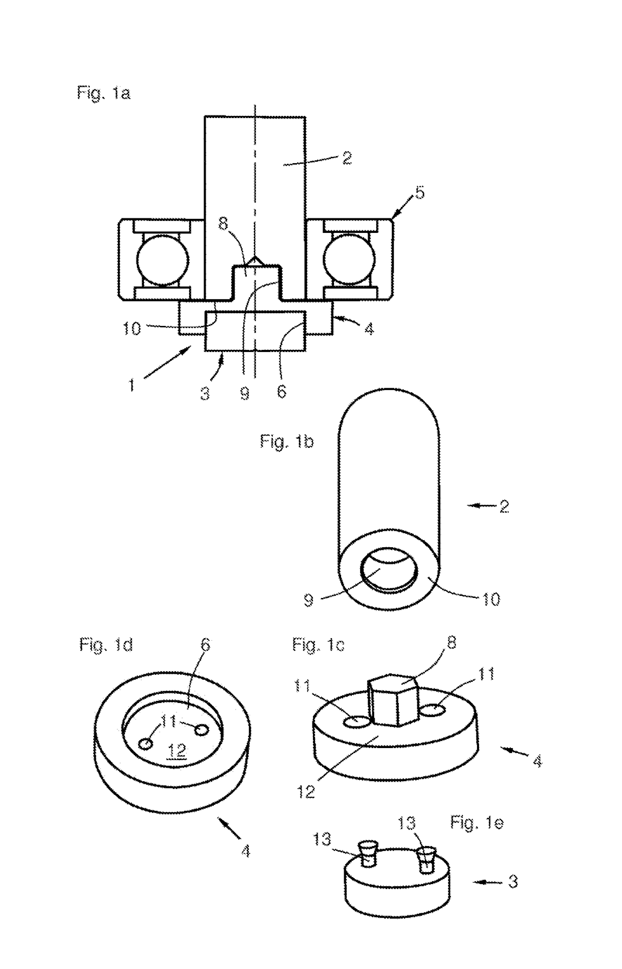
[0036]FIG. 1a shows the magnet sensor assembly 1, which is mounted on a shaft end of a shaft 2. The magnet sensor assembly 1 consists of a magnet sensor 3 and an adapter 4. Further illustrated is a ball bearing 5, with which the shaft 2 is mounted in a drive housing not shown here. In this embodiment, the adapter 4 is provided with a receptacle 6 for the magnet sensor 3, which receptacle is designed to be substantially cylindrical. In the example shown, the magnet sensor is only partially sunk into the receptacle 6. The adapter 4 includes a pin-shaped protrusion 8, which is pressed axially into a cavity 9 in the shaft end of the shaft 2.
[0037]FIG. 1b shows a three-dimensional illustration of the shaft 2, with the cavity 9, which is designed as a cylindrical blind hole here.
[0038]FIG. 1c shows the disc-shaped adapter 4, with the pin 8, and a wall 12, in which two recesses 11 are also formed. The pin 8 has a slightly larger diameter than the cavity 9 of the shaft (FIG. 1b) to promote ...
second embodiment
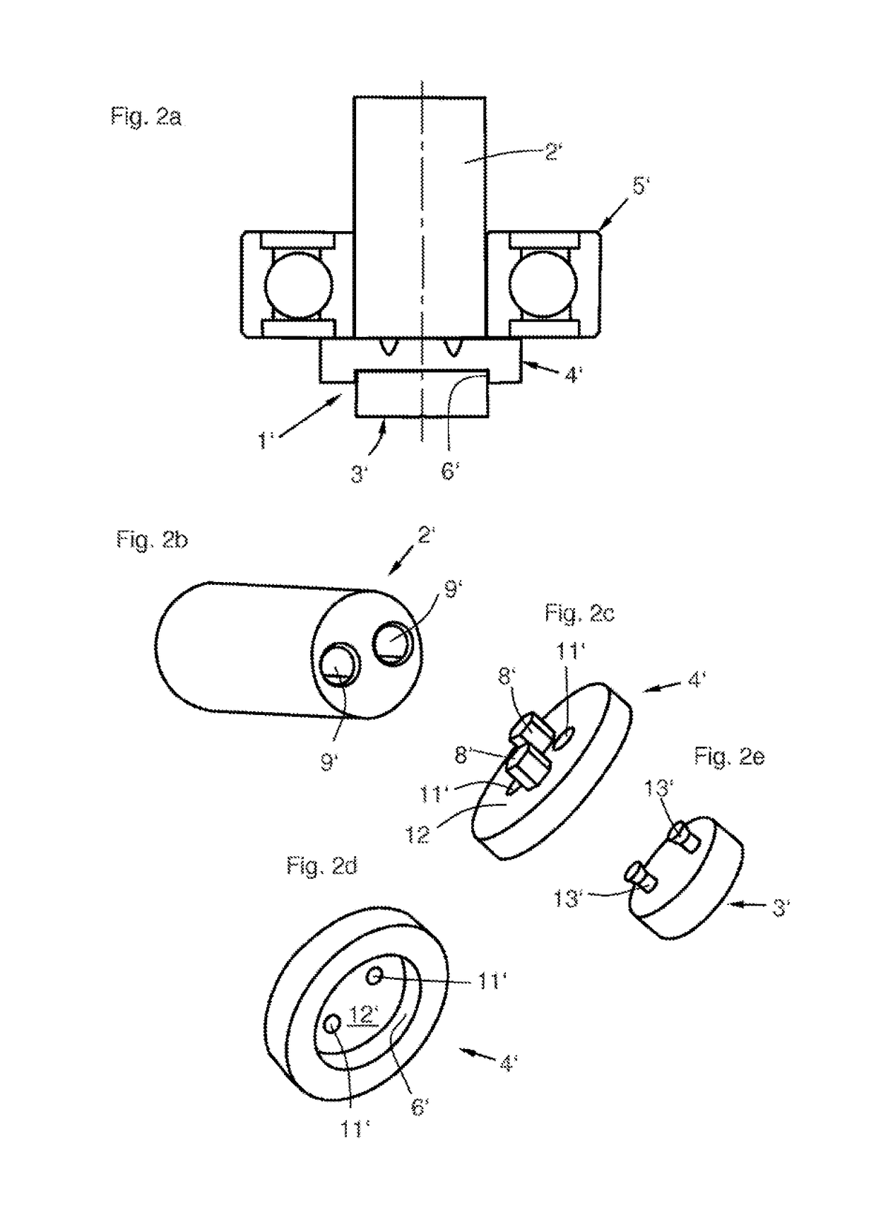
[0042]FIG. 2a shows the magnet sensor assembly 1′, with a magnet sensor 3′, an adapter 4′, a bearing 5′, and a shaft 2′. The magnet sensor 3′ is accommodated in a receptacle 6′ of the adapter and connected to the latter in a form-fit manner (not visible here) using a process similar to that discussed above.
[0043]FIG. 2b shows a second embodiment of the shaft 2′, which comprises two cavities 9′, which extend parallel to each other and to the longitudinal axis of the shaft 2′ into the shaft 2′.
[0044]FIG. 2c shows a second embodiment of the adapter 4′, with two pin-like protrusions 8′ and two recesses 11′, which are expanded conically and are apertures through a wall 12′. The length of the protrusions 8′ is slightly less than the depth of the cavities 9′ of the shaft 2′ (FIG. 2b).
[0045]FIG. 2d shows the adapter 4′ alternatively from another perspective, with a receptacle 6′ for the magnet sensor, the wall 12′, and the recesses 11′, which have a smaller cross section here than on the op...
third embodiment
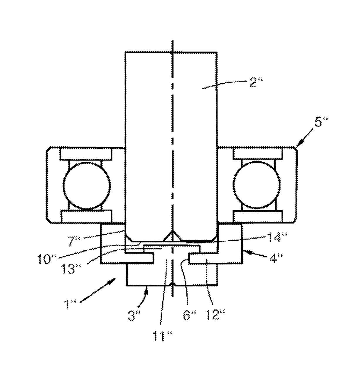
[0047]FIG. 3a shows the magnet sensor means 1″, with a shaft 2″, an adapter 4″, a magnet sensor 3″, and a ball bearing 5″. In this case, the adapter is pressed onto a section of an outer circumferential region 7″ of the shaft 2″ and is designed to be pot-shaped in its basic form, wherein a recess 11″ exists in the pot-shaped bottom, which recess also forms a receptacle 6″ for the magnet sensor. The largest portion of the magnet sensor 3″ is however free. From this exposed region of the magnet sensor 3″, a protrusion 13″ extends axially, which has an expansion at its end in order to establish a form fit with a wall 12″ of the adapter 4″. Between an end face 10″ of the shaft and the magnet sensor 3″ is provided a distance 14″, which improves the degree of efficiency of the sensor magnetic circuit.
[0048]FIG. 3b shows a third embodiment of the shaft 2″, which does not have any special receptacle geometries for the adapter, which is merely pressed onto the outer circumferential region 7″...
PUM
| Property | Measurement | Unit |
|---|---|---|
| non-magnetic | aaaaa | aaaaa |
| magnetic | aaaaa | aaaaa |
| chemical resistance | aaaaa | aaaaa |
Abstract
Description
Claims
Application Information
 - R&D
- Intellectual Property
- Life Sciences
- Materials
- Tech Scout
- Unparalleled Data Quality
- Higher Quality Content
- 60% Fewer Hallucinations
Browse by: Latest US Patents, China's latest patents, Technical Efficacy Thesaurus, Application Domain, Technology Topic, Popular Technical Reports.
© 2025 PatSnap. All rights reserved.Legal|Privacy policy|Modern Slavery Act Transparency Statement|Sitemap|About US| Contact US: help@patsnap.com


