Rotor blade for a turbine

a turbine and rotor blade technology, applied in machines/engines, renewable energy generation, greenhouse gas reduction, etc., can solve the problems of short assembly time on site and inability to optimize energy generation, and achieve the effect of short assembly time, easy pre-assembling, and secure in pla

Active Publication Date: 2017-10-24
ANDRITZ HYDRO GMBH
View PDF11 Cites 0 Cited by
  • Summary
  • Abstract
  • Description
  • Claims
  • Application Information

AI Technical Summary

Benefits of technology

[0004]The invention is thus characterized in that the rotor blade has a cavity and at least two ribs at its lower end, where a journal is provided for connecting to the hub of a turbine rotor that is inserted through an exactly fitting opening in the bottommost rib into the lower end of the rotor blade and reaches as far as the topmost rib, where it is inserted into a recess, and which is form-locked and / or force-locked with the ribs, where the journal has at least one cone or ledge and is connected to it with a rib in a force-locked connection. The blade thus has adequate stability, ever if the lower end has a smaller diameter, where the proportion of the total length of the rotor blade used for energy generation can be increased substantially. As a result of the firm connection between journal and rotor blade, torques can also be transferred effectively in addition to bending moments.
[0005]A favorable embodiment of the invention is characterized in that the blade is made of steel. The blade can be made much smaller as a result. It may be welded out of sheet steel, however the base can also he a casting should the situation arise.
[0011]The invention also relates to a turbine, especially a tidal current turbine with at least two, preferably three, rotor blades set up as described above. A stable rotor blade is needed especially for tidal current turbines, where the rotor blade according to the invention has the advantage of good conversion of energy within a very small space. Several blades may also be provided. The steel design, in particular, provides a compact and stable construction for tidal current turbines or run-of-river turbines.
[0011]The invention also relates to a turbine, especially a tidal current turbine with at least two, preferably three, rotor blades set up as described above. A stable rotor blade is needed especially for tidal current turbines, where the rotor blade according to the invention has the advantage of good conversion of energy within a very small space. Several blades may also be provided. The steel design, in particular, provides a compact and stable construction for tidal current turbines or run-of-river turbines.
[0008]If, preferably, a retaining ring is provided that can be joined in a form-locked connection to the other cone or ledge, the blade can be secured in place easily and the forces transferred.
[0009]A development according to the invention is characterized in that tie rods connected to at least one rib are provided. In this way, the fastening devices can be pre-assembled easily, resulting in shorter assembly times on site. It is especially favorable if the journal is joined to the at least two ribs in a force-locked connection by pre-stressing the tie rods.
[0008]If, preferably, a retaining ring is provided that can be joined in a form-locked connection to the other cone or ledge, the blade can be secured in place easily and the forces transferred.
[0008]If, preferably, a retaining ring is provided that can be joined in a form-locked connection to the other cone or ledge, the blade can be secured in place easily and the forces transferred.
[0011]The invention also relates to a turbine, especially a tidal current turbine with at least two, preferably three, rotor blades set up as described above. A stable rotor blade is needed especially for tidal current turbines, where the rotor blade according to the invention has the advantage of good conversion of energy within a very small space. Several blades may also be provided. The steel design, in particular, provides a compact and stable construction for tidal current turbines or run-of-river turbines.

Problems solved by technology

Thus, the contour of the blade must also be adapted to these geometrical dimensions and cannot be optimized for energy generation.
In this way, the fastening devices can be pre-assembled easily, resulting in shorter assembly times on site.

Method used


Image

  • Rotor blade for a turbine
  • Rotor blade for a turbine
  • Rotor blade for a turbine

Examples


Embodiment Construction

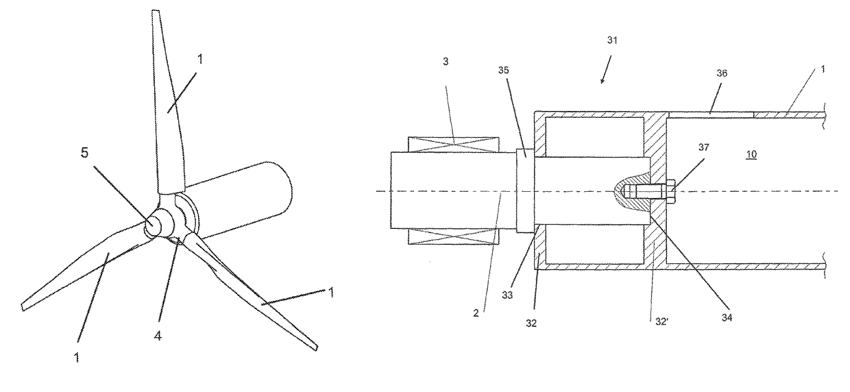
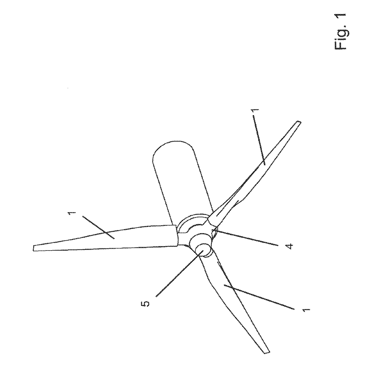
[0021]FIG. 1 shows an arrangement for a turbine as is used to utilize energy from tidal currents. This turbine has, for example, three rotor blades 1, which are connected to the shaft 5 via hub 4. However, two, four, or more blades can also be used.

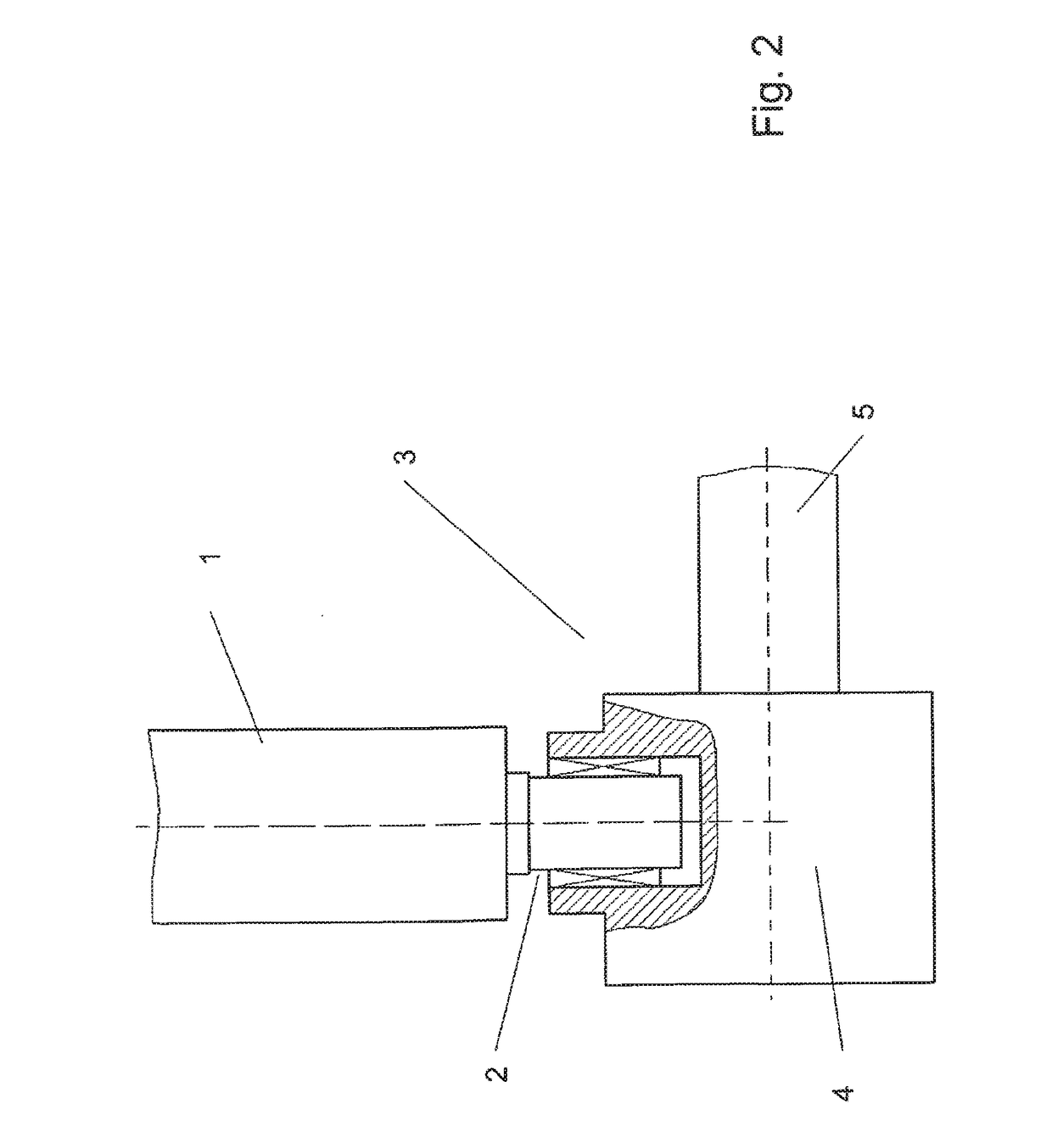
[0022]FIG. 2 shows how a rotor blade 1 is connected to the shaft 5. Here, the journal 2 of the rotor blade 1 is secured via a bearing or other fastening 3 in the hub 4, which is connected permanently to the shaft. Here, devices may be provided that can be used to rotate the rotor blade in the current for optimum energy generation.

[0023]FIG. 3 now shows a variant according to the invention of the connection between the journal 2 and the rotor blade 1. The lower end 31 of the rotor blade 1 contains power transmission elements, which are shaped as ribs 32, 32′, in the cavity 10. The journal 2 is inserted through an exactly fitting opening 33 in the bottommost rib 32 into the lower end 31 of the rotor blade 1 and reaches as far as the topmost...


PUM


Abstract

An assembly of rotor blades and hub for a turbine, such as a tidal current turbine. Each rotor blade includes a cavity and at least two ribs extending into the cavity at a radially inward (lower) region of the rotor blade. The hub includes a journal for each blade and the journal extends into the cavity and is supported by the at least two ribs.

Description

RELATED APPLICATION[0001]This is a U.S. National Phase of PCT / EP2013 / 000125 filed 17 Jan. 2013, which designated the U.S and claims priority to Austrian application no. A 62 / 2012 filed 20 Jan. 2012, the entirety of each of these applications are incorporated by reference.BACKGROUND AND SUMMARY OF INVENTION[0002]The present invention relates to a rotor blade for a turbine, where the rotor blade (1) has a cavity (10). Turbines of this type include wind turbines, ocean current turbines, and tidal current turbines.[0003]At the base, i.e. at the connection to the turbine hub, the rotor blades are exposed to very high torques, which requires very large and expensive flanged connections, also in order to guarantee the necessary stiffness. Flange connections of this kind are known from WO 2010 / 084320 A2 or WO 2011 / 077454, for example. Thus, the contour of the blade must also be adapted to these geometrical dimensions and cannot be optimized for energy generation. In addition, there are blad...

Claims


Application Information

Patent Timeline
Patent Type & Authority Patents(United States)
IPC IPC(8): F03D1/06F03B3/12F03B13/26F01D5/30
CPCF03D1/0658F01D5/3053F03B3/121F03B13/264Y02E10/721F05B2260/30Y02E10/223Y02E10/28B64C11/04F03B3/06F03B3/123F03B3/128F03B3/14F03D1/0675F03D1/0691Y02E10/20Y02E10/72Y02E10/30
Inventor GEROMILLER, JOHANNESPLESSING, DANIELHERMANN, CARSTEN
Owner ANDRITZ HYDRO GMBH
Why Eureka
Try Eureka