

Automatically-closing connector for connecting a liquid injection head to an injection outlet
a technology of automatic closing and connector, which is applied in the direction of tube connector, lock casing, catheter, etc., can solve the problems of running the risk of said pathway subsequently being blocked by coagulated blood, and achieve the effect of simple structur
- Summary
- Abstract
- Description
- Claims
- Application Information
AI Technical Summary
Benefits of technology
Problems solved by technology
Method used
Image

Examples
Embodiment Construction
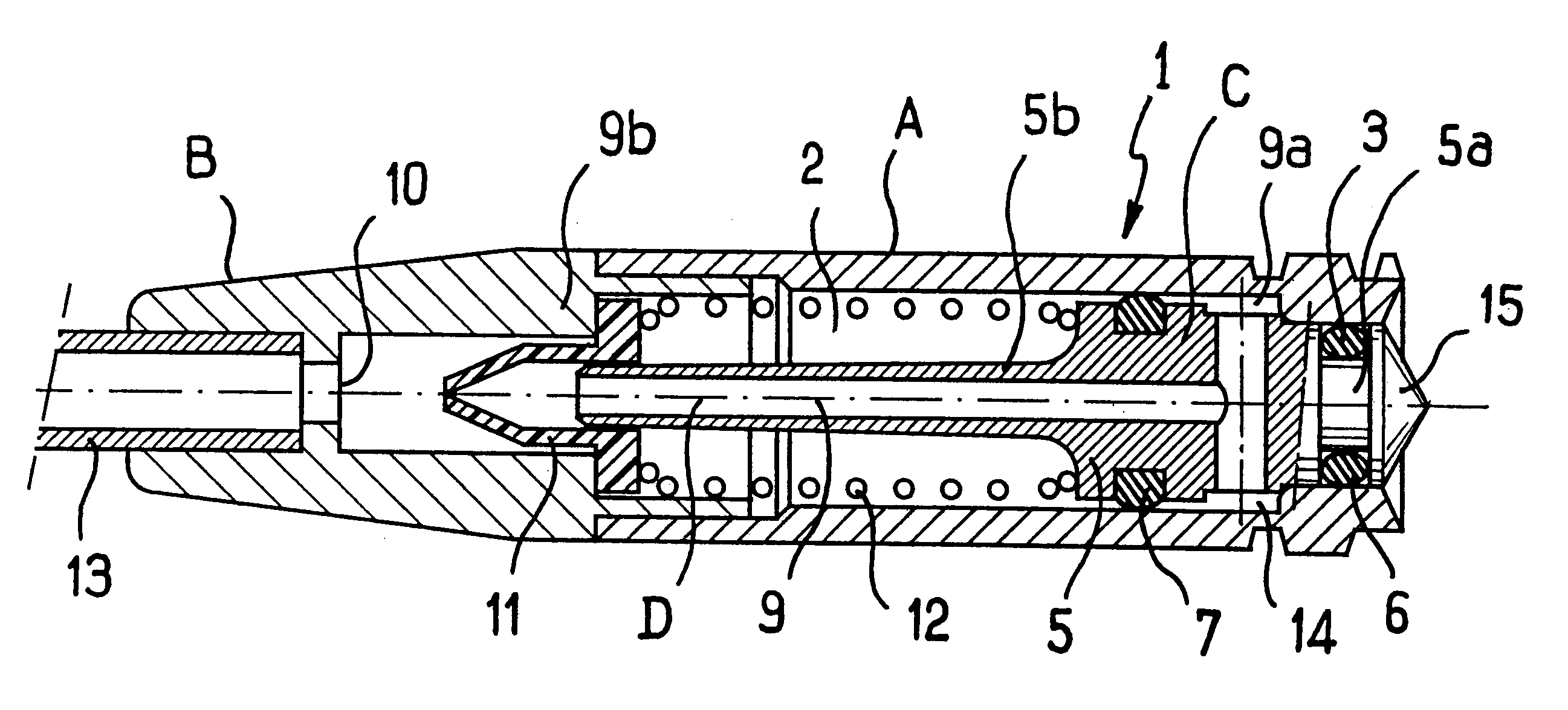
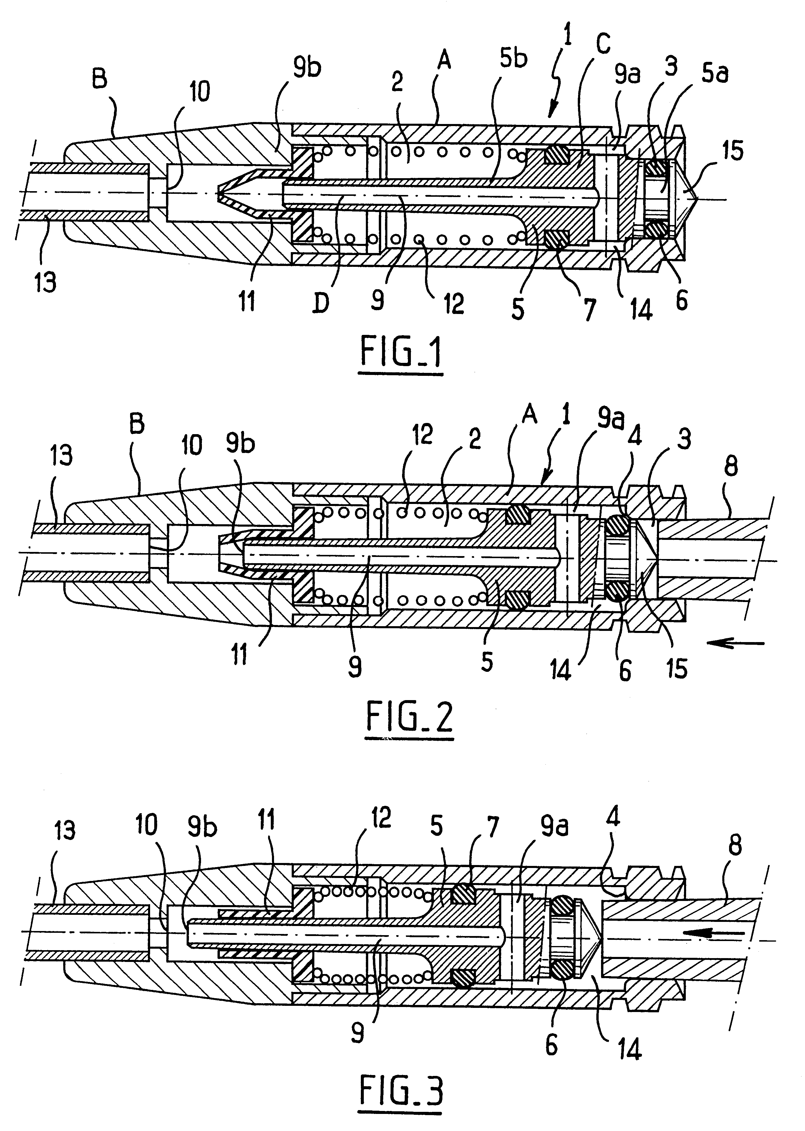
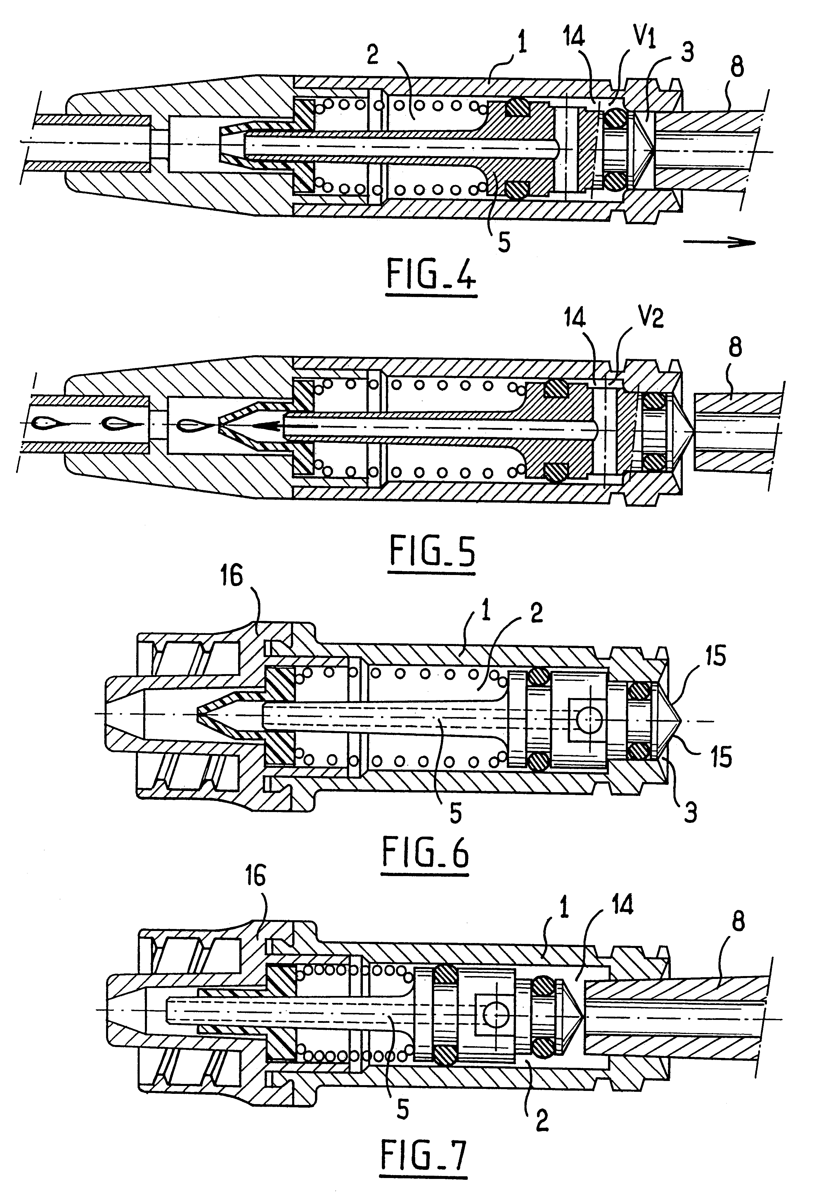
In the figures, elements that are identical or that correspond are designated by references that are identical or that are associated with the prime symbol.
The connectors shown in FIGS. 1 to 5 comprise a case (1) and a closing piston (5).
The case (1) defines a housing (2) that is accessible by a tubular inlet duct (3), the housing and the duct being cylindrical and on the same axis, but the right section of the housing being greater than that of the duct such that an annular shoulder (4) exists where the duct joins the chamber and constitutes an end wall at one end of the housing.
The closing piston (5) is movable in translation in the housing and in the duct, said piston carrying an upstream sealing gasket (6) in the form of an annular gasket that provides lateral sealing for the portion (5a) of the piston which moves in the inlet duct, and a downstream sealing gasket (7) in the form of an annular gasket which provides lateral sealing for the portion (5b) of the piston which moves i...
PUM
 Abstract
Description
Claims
Application Information