Weighing scale with a combined sealing and arresting device

a technology of sealing and arresting device and weighing scale, which is applied in the direction of measuring device, weighing apparatus, instruments, etc., can solve the problems of accuracy degradation and achieve the effect of preserving the accuracy of the scal

Inactive Publication Date: 2003-07-29
METTLER TOLEDO GMBH
View PDF11 Cites 20 Cited by
  • Summary
  • Abstract
  • Description
  • Claims
  • Application Information

AI Technical Summary

Benefits of technology

It is therefore the objective of the present invention to further develop a scale of the type described above by providing arrestment and sealing means that can be alternated rapidly between the applied and released state and are effective in preserving the accuracy of the scale in the presence of the aforementioned conditions.
A solution of this kind is of twofold benefit: On the one hand, the concept of expanding and contracting an elastic device, which could be a spring, allows the movable part to be arrested against the fixed part either by a form-fitting engagement (where the elastic device expands into a counterpart of a matching concave shape) or by a friction-based engagement. On the other hand, when the elastic device is in its expanded state, it can also form a seal.
The ability to function as a seal is realized in particular with an arrangement where the elastic device forms a hollow space for a fluid and the expansion and contraction is effected by increasing or decreasing the amount of fluid contained in the hollow space. In practice, this can be achieved by providing a device for selectively moving fluid into and out of the hollow space. This also represents a simple way of activating and deactivating the device.
The sealing function is achieved most efficiently by arranging the elastic device at the place where the load-transmitting member passes through an opening in the scale housing. This has the advantage, that the seal is provided in the immediate area where the functionally required opening in the scale housing is located. It would of course be conceivable to arrange the seal somewhere more in the interior of the scale and to provide a dirt-collecting chamber, but the arrangement of the seal at the periphery of the housing proves to be more advantageous.
In order to achieve the largest possible area of pressurized contact between the fixed part and the movable part, it is advantageous if the ring-shaped support has a convex-curved contour shape facing towards the movable part, with a contour radius about equal to the ring diameter of the cushion. The convex surface shape of the cushion produces a particularly effective sealing interface compared, e.g., to a mere line contact between the fixed part and the movable part.
The contact engagement of the elastic device between the fixed part and the movable part creates the danger that the movable part will be exposed to non-symmetric forces that could be harmful or even destructive to the weighing cell. It is therefore advantageous to use a design feature that will allow a certain amount of play in the horizontal directions.

Problems solved by technology

Second, it is a known fact that scales are often used in a dirty environment and that, furthermore, the materials themselves that are being weighed can contaminate a scale and thereby cause its accuracy to deteriorate.

Method used


Image

  • Weighing scale with a combined sealing and arresting device
  • Weighing scale with a combined sealing and arresting device
  • Weighing scale with a combined sealing and arresting device

Examples


Embodiment Construction

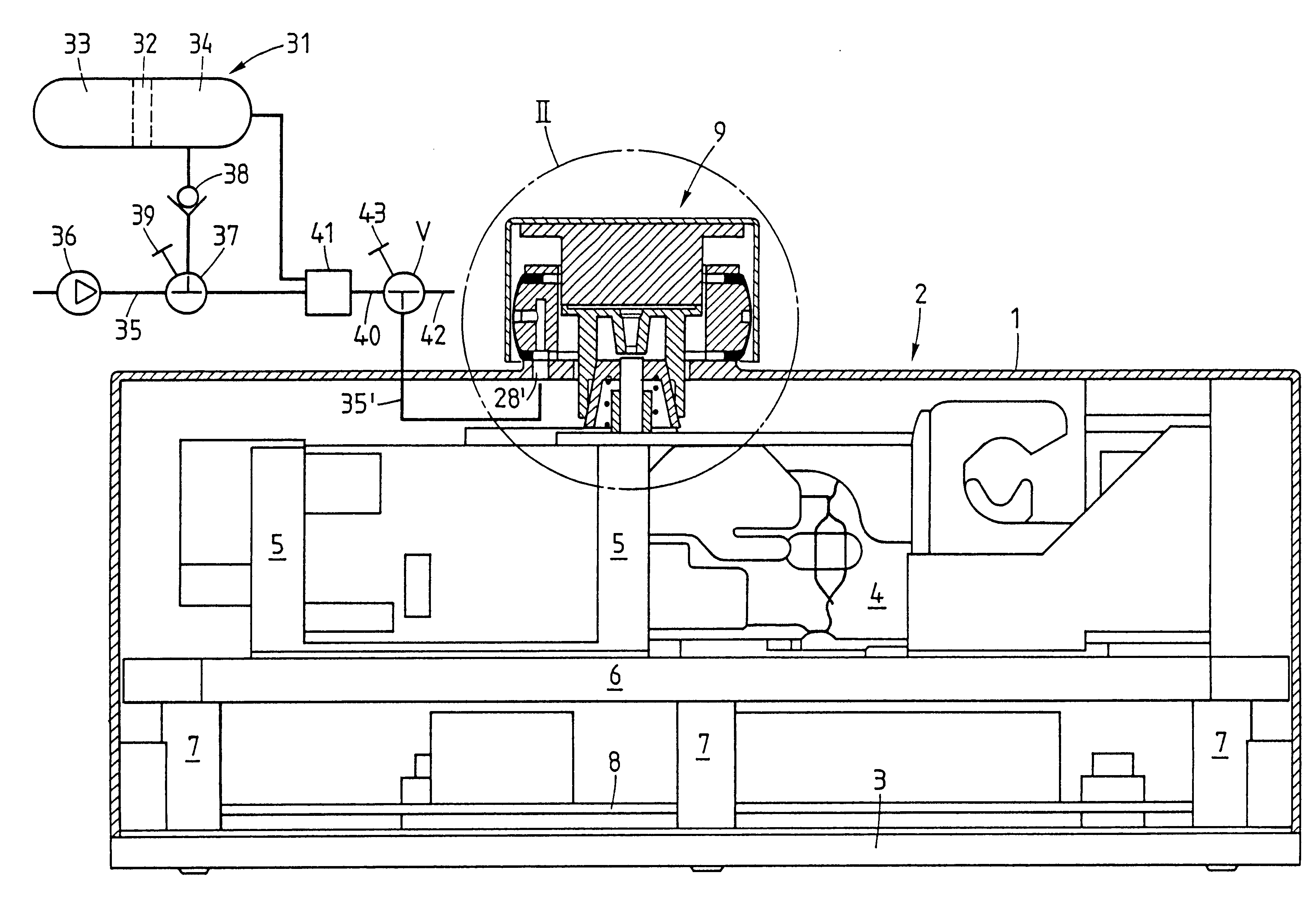
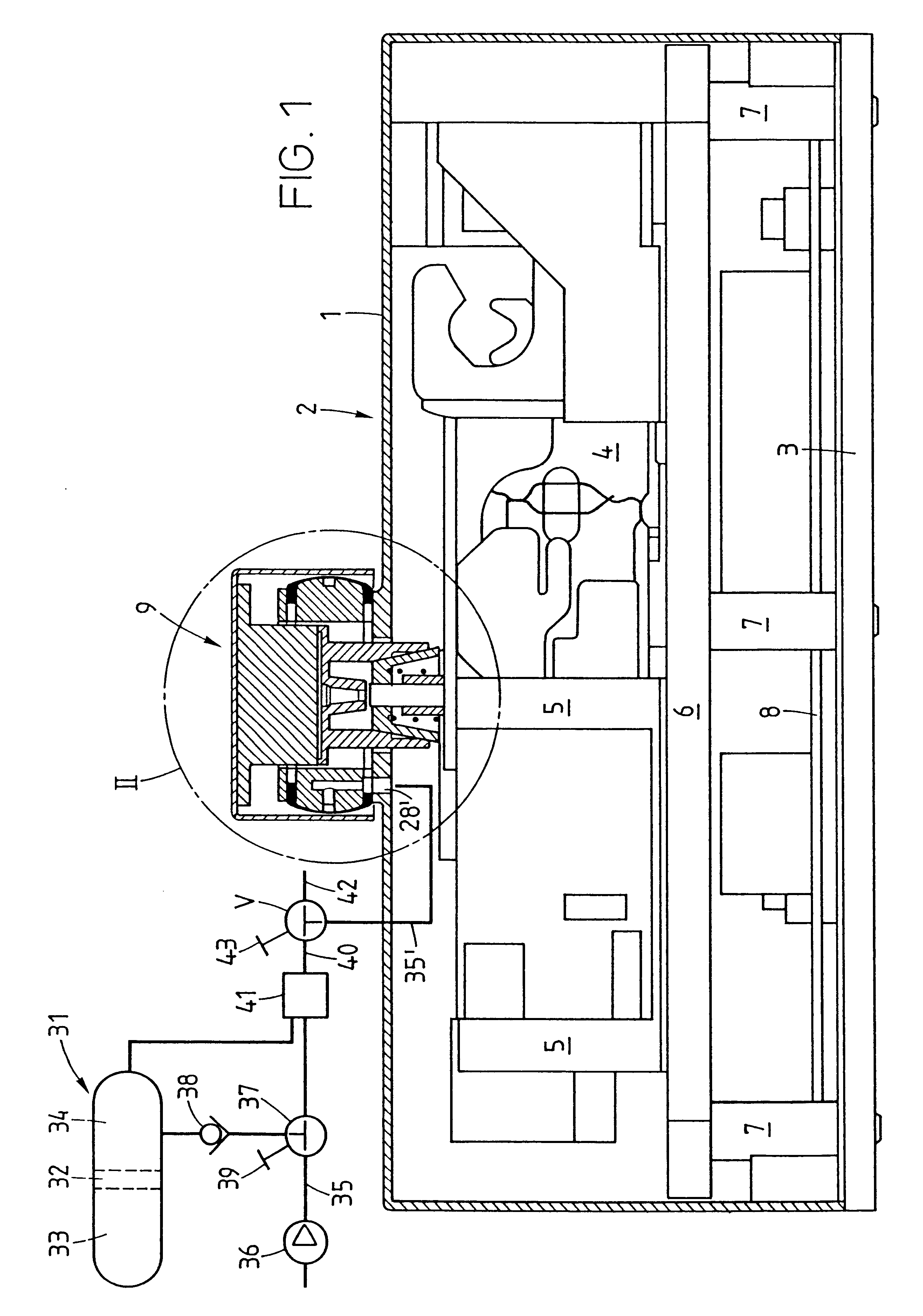
FIG. 1 gives a schematic view of a scale 2, e.g., a conveyor-belt scale installed below a weighing section of a conveyor belt. The scale housing 1 is seated on a base 3. The scale housing 1 encloses a force transducer 4 of a design that is known per se, preferably of a type where a block containing the lever-reduction mechanism is mounted on a plate 6 by means of brackets 5. The plate 6, in turn, is supported from below on posts 7. The space below the plate 6 is occupied by the electronic circuitry required to perform the weighing process, for example a circuit board module 8.

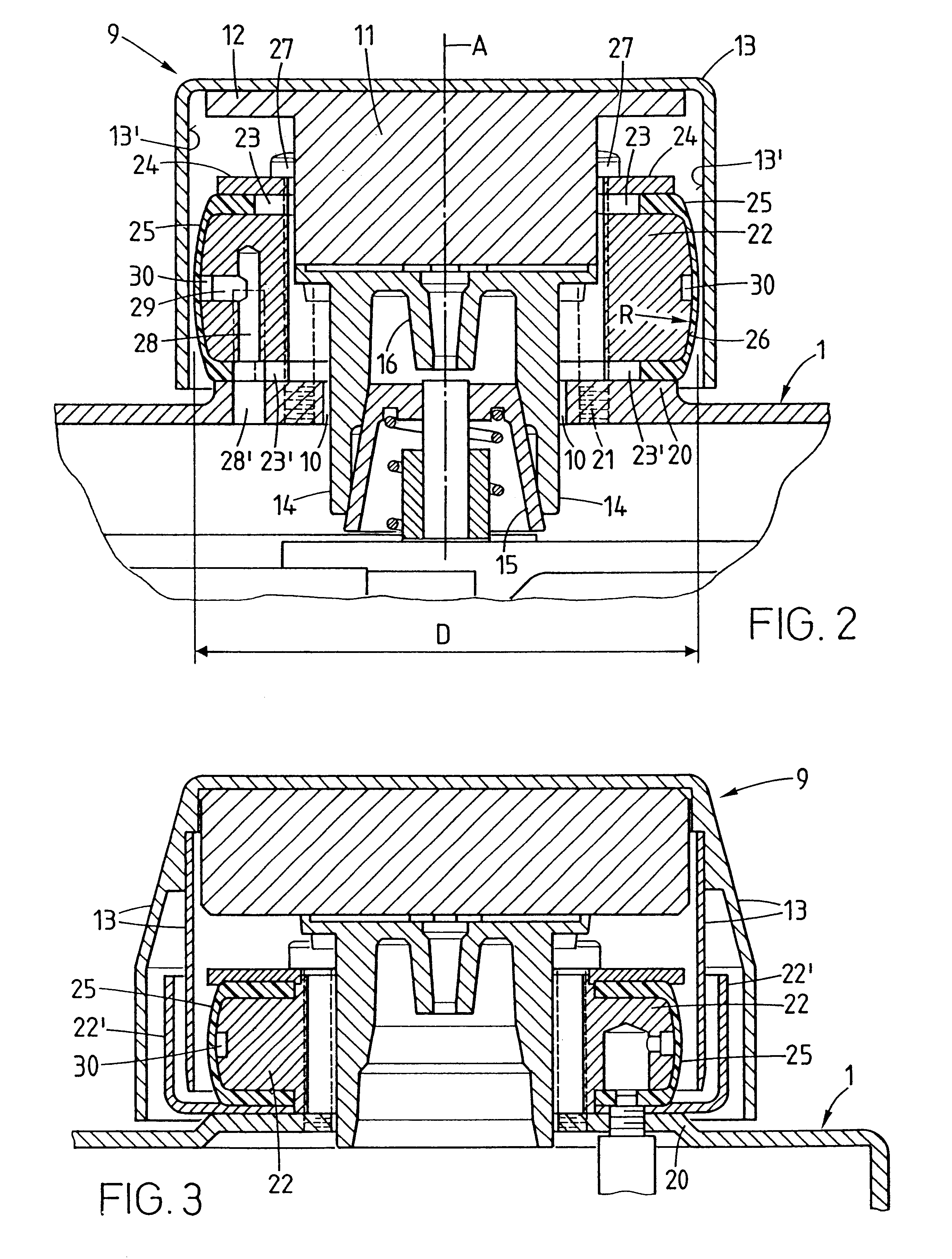
A load-transmitting member 9, shown in an enlarged view in FIG. 2, protrudes like a large push-button on the topside of the scale housing. The load-transmitting member extends in the direction of an axis A and passes through a coaxial opening 10 of the scale housing 1 to transmit the force from the weighing load to the force transducer 4. Thus, FIG. 2 in particular illustrates that the load-transmitting member ...


PUM


Abstract

A weighing scale has a housing (1) that encloses a force transducer (4). A load-transmitting member (9) is connected to the force transducer (4) and passes through an opening to the outside of the housing to transmit the weighing load to the force transducer. An elastic device is interposed between a fixed part that is attached to the housing (1) and a movable part that is attached to the load-transmitting member (9). The elastic device is preferably hollow and controllably expandable and contractible by injecting and removing a fluid through a conduit system (31-43) with a selectively switchable valve device.

Description

The invention relates to a weighing scale (hereinafter called a scale, for short) in the general sense of a weighing device with a housing. Inside the housing is a force transducer, and connected to the latter is a load-transmitting member that passes through an opening in the housing and serves to transmit the weighing load to the force transducer. With scales of this type, the following two concerns need to be addressed: First, when the scale is not in use, it may be desirable to immobilize the movable parts inside the scale with an arrestment device for protection against random forces that could be detrimental to the accuracy of the scale. Second, it is a known fact that scales are often used in a dirty environment and that, furthermore, the materials themselves that are being weighed can contaminate a scale and thereby cause its accuracy to deteriorate. Many applications require that the process of applying and releasing the arrestment can be performed in rapidly alternating su...

Claims


Application Information

Patent Timeline
Patent Type & Authority Patents(United States)
IPC IPC(8): G01G23/02G01G23/00G01G21/30G01G23/08
CPCG01G23/02
Inventor ISELI, MARC
Owner METTLER TOLEDO GMBH
Why Eureka
Try Eureka