
Centrifuge with open conveyor and methods of use

a technology of centrifuge and open conveyor, which is applied in the field of centrifuges, can solve the problems of reducing the clarification capability of the centrifuge, requiring a lot of energy to process the mixture, and requiring a large physical size of the centrifuge, so as to reduce the turbulence

Inactive Publication Date: 2003-08-12
TUBOSCOPE IP
View PDF93 Cites 39 Cited by
  • Summary
  • Abstract
  • Description
  • Claims
  • Application Information

AI Technical Summary

Benefits of technology

The present invention, in certain aspects, discloses a new decanting centrifuge which has a rotatable bowl within which rotates a caged conveyor at a different speed than the speed of rotation of the bowl. In certain aspects a caged or skeleton conveyor according to the present invention includes a plurality of spaced-apart flights within which and to which are secured a plurality of spaced-apart support beams, rods, or members so that fluid can flow freely with reduced turbulence between the beams, rods or members, into and out from the interior of the conveyor. The flights form a screw portion of the conveyor for conveying solids separated from fluid to be treated by the centrifuge from one end of the bowl to the other (at which there are one or more solids outlets). In one aspect the flights are in the form of a helix.
In certain embodiments fluid flows through the chamber and impacts a plurality of impellers that are connected to and rotate with the conveyor. The fluid impacts the impellers and is then moved radially outward by the blades toward the conveyor's flights. The impellers are configured and positioned to radially accelerate the fluid so that as the fluid passes the impellers outer edges, the fluid's speed (radial speed) is near or at the speed of a pool of material within the bowl--thus facilitating entry of this fluid into the pool or mass of fluid already in the bowl. By reducing or eliminating the speed differential between fluid flowing from the acceleration chamber and fluid already present in the bowl, turbulence is reduced, entry of solids of the entering fluid into the pool in bowl is facilitated, and more efficient solids separation results.
Such centrifuges with reduced fluid turbulence, particularly at points or areas at which fluid exits a conveyor to enter a bowl;
Such centrifuges which effect increased settling and separation of solids.

Problems solved by technology

To accommodate such feed rates, high torques are encountered, much energy is required to process the mixture, and the physical size of the centrifuge can become enormous.
As larger feed volumes are processed in a given centrifuge machine, the clarification capability of the centrifuge decreases due to decreased retention or residence time, partial-acceleration or nonacceleration (slippage) of the feed fluid (the solids / liquid mixture), radial deceleration of the fluid moving through the conveyor, and turbulence created by the movement and / or focusing of large volumes of fluid through ports that tend to transmit and / or focus a high volume flow in an area exterior to the conveyor that induces undesirable turbulence in that area and results in excess wear and abrasion to parts that are impacted by this flow.
This relatively high speed fluid is, therefore, turbulent and can wear away parts of the acceleration chamber.
Also exiting from the acceleration chamber via exit ports this turbulent-relatively-high-speed fluid can inhibit the desired flow of separated solids both in the bowl toward the solids exit ports and toward the beach area and can wear away parts of the conveyor and bowl adjacent the acceleration chamber exit ports.

Method used


Image

  • Centrifuge with open conveyor and methods of use
  • Centrifuge with open conveyor and methods of use
  • Centrifuge with open conveyor and methods of use

Examples


Embodiment Construction

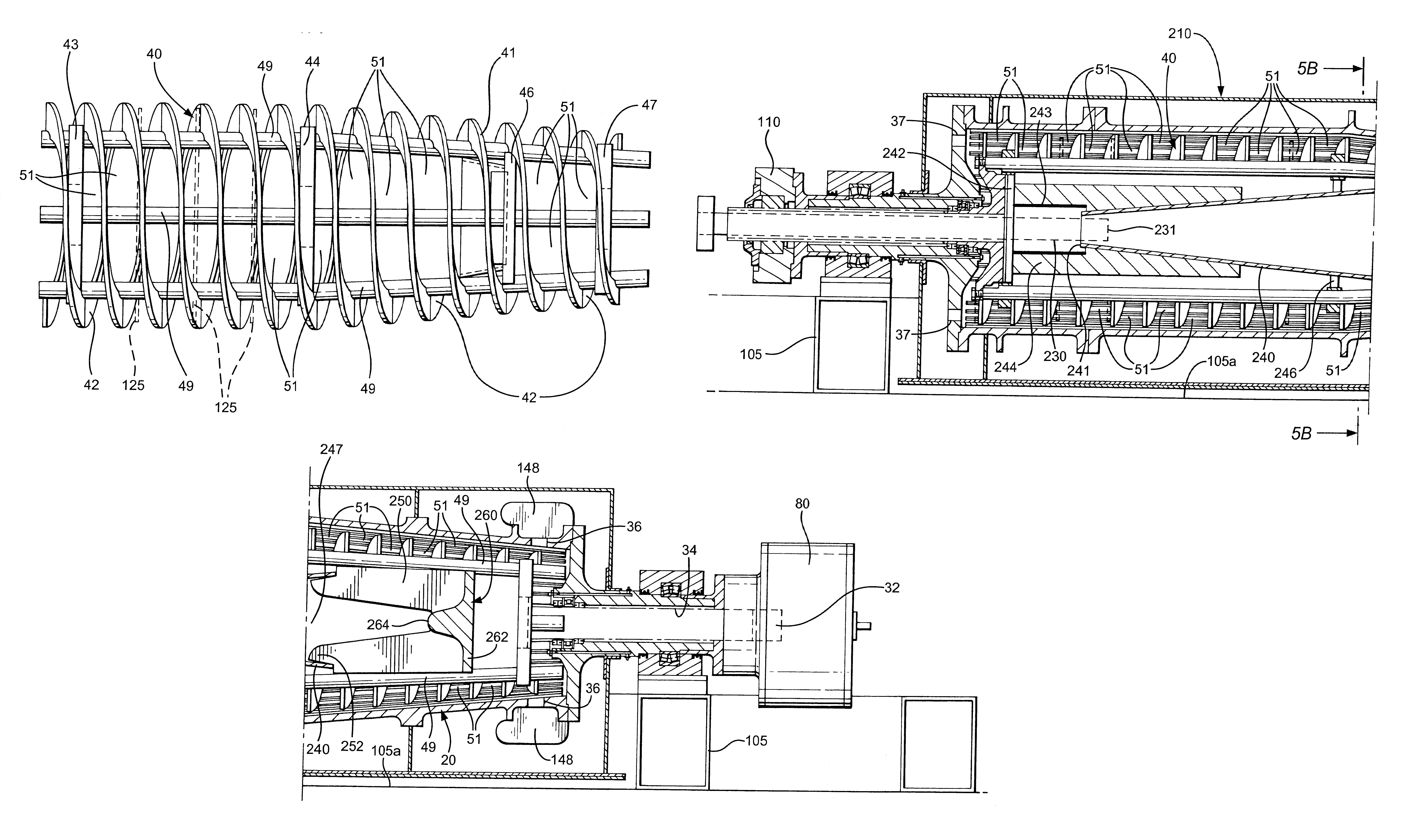
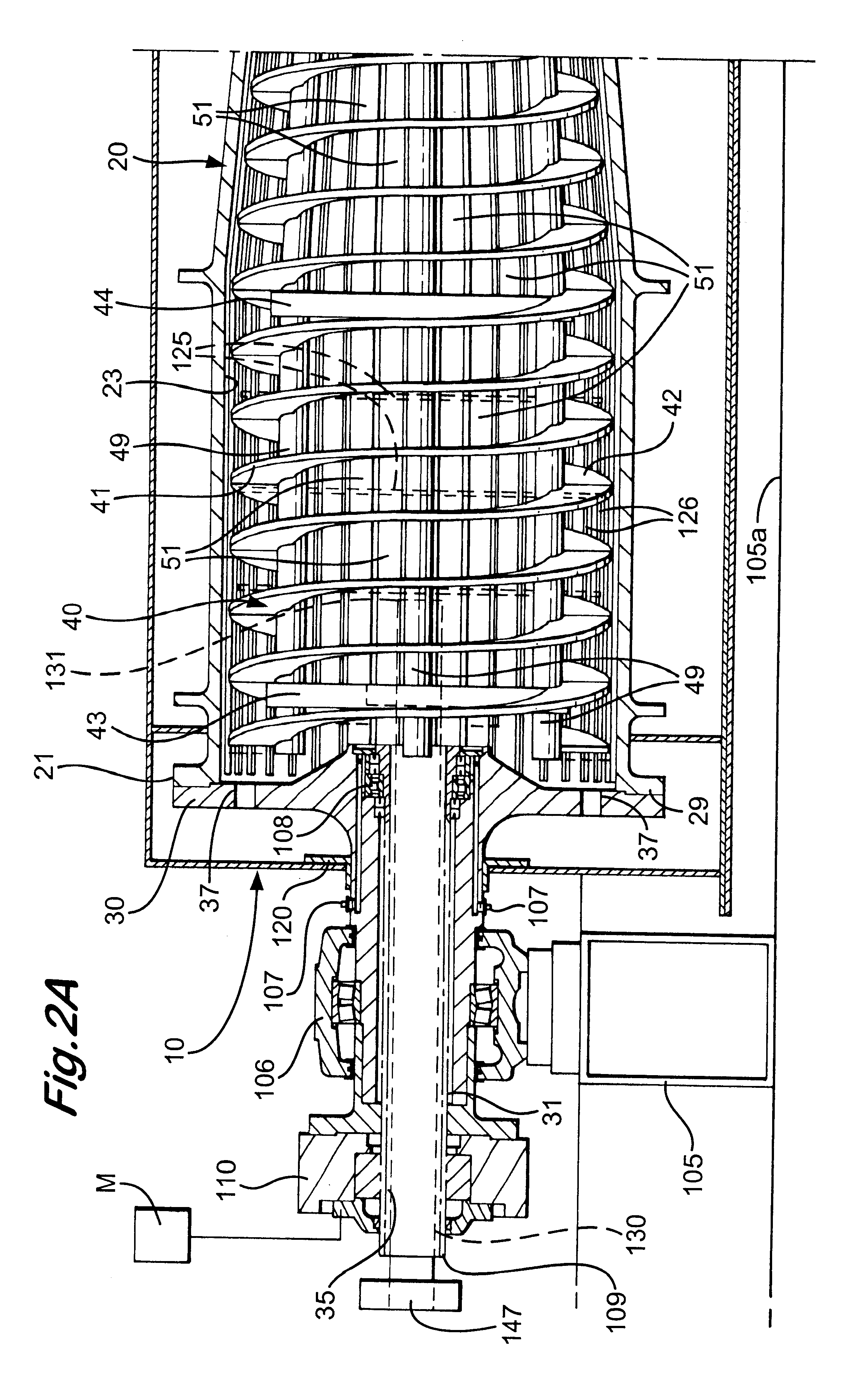
FIGS. 2A and 2B show a decanting centrifuge 10 according to the present invention which has an outer housing 12 within which is rotatable mounted a bowl 20 with a hollow interior 23. Within the hollow interior 23 of the bowl 20 is rotatably mounted a conveyor 40 that has a continuous helix or screw 41 that extends from a first end 21 of the bowl 20 to a second end 22 of the bowl 20. Supports 105 on a base 105a support the centrifuge (bowl, conveyor, outer housing, and other components). The supports 105 may themselves be supported on a skid.

A plurality of support rods 49 are disposed within the helix 41 and are connected at points of contact to flights or sections 42 of the helix 41, e.g. by bolting and / or welding. The flights 42 are sized so that they are separated a desired distance from the interior surface of the bowl 20 along the bowl's length. As is well known, the edges of the flights may be lined with side-by-side pieces or tiles made of sintered tungsten carbide or the edge...


PUM


Abstract

A conveyor for a centrifuge and a centrifuge with such a conveyor, the conveyor having a plurality of spaced-apart flight members spaced apart along its length, a plurality of support members extending between, and connected to the flight members, the support members spaced-apart around the flight members, the members and support members defining a plurality of open areas through which fluid to be treated by the centrifuge is flowable from within the conveyor out into the bowl. In one aspect, a fluid velocity decreasing chamber is provided between an exit tube end and impeller apparatus for radially accelerating the fluid with the conveyor. In certain aspects the open "caged" conveyor structures diffuses fluid flow from the conveyor so that a dispersed unfocused flow of fluid exits the conveyor into the bowl, and, in one particular aspect with feed from within the conveyor to space adjacent a beach area of the bowl.

Description

1. Field of the InventionThis invention relates generally to centrifuges, and more particularly to decanting centrifuges with a rotating bowl and scroll.2. Description of Related ArtThe prior art discloses a variety of decanter centrifuges or "decanters" which, in many embodiments, include a rotating centrifuge bowl rotating at one speed and in which a screw conveyor ("scroll") revolves at a slightly different speed. Such centrifuges are capable of continuously receiving feed in the bowl and of separating the feed into layers of light and heavy phase materials (e.g. liquids and solids) which are discharged separately from the bowl. The screw conveyor structure, rotating at a differential speed with respect to the bowl, moves or "scrolls" an outer layer of heavy phase or solids slurry material to a discharge port or ports usually located in a tapered or conical end portion of the bowl. Centrifugal force tends to make the light phase material discharge through one or more ports usuall...

Claims


Application Information

Patent Timeline
Patent Type & Authority Patents(United States)
IPC IPC(8): B04B1/00B04B1/20
CPCB04B1/20B04B1/2016B04B2001/2033B04B2001/2041B04B2001/2058
Inventor KOCH, RICHARD JAMESSEYFFERT, KENNETH W.WRIGHT, JOHN PATRICKMITRA, SUBRATA
Owner TUBOSCOPE IP
Features
  • Generate Ideas
  • Intellectual Property
  • Life Sciences
  • Materials
  • Tech Scout
  • Unparalleled Data Quality
  • Higher Quality Content
  • 60% Fewer Hallucinations
Learn More