Method of spinning-in yarn on an operating unit of a rotor spinning machine and a device for carrying out the method

a technology of rotor spinning machine and operating unit, which is applied in the direction of yarn, open-end spinning machine, textiles and paper, etc., can solve the problems of increasing the purchase cost, complicated attendance devices, and increasing the purchase cos

Inactive Publication Date: 2003-08-19
RIETER CZ AS
View PDF4 Cites 5 Cited by
  • Summary
  • Abstract
  • Description
  • Claims
  • Application Information

AI Technical Summary

Benefits of technology

The increase in the piecer quality and the reduction of the attendance time required for the spinning-in operation on an operating unit is obtained by the method according to the invention whose principle consists in that at least some of the final spinning-in steps are timed in relation to the closing of the spinning unit thus obtaining optimum piecer quality repeatedly at all operating units of the machine
In manually operated machines, the method according to the invention eliminates the operator's intervention into the process proper of attaching the yarn at the resumption of spinning and permits exactly the synchronization (timing) of the final spinning-in steps, this timing being on all operating units repeatedly (invariably) the same. In automated rotor spinning machines, this method permits reduction of the attendance interval of the attending device.
In particular, in manually attended machines with manual closing of the spinning unit, it is advantageous if the steps of the yarn preparation for spinning-in and the steps of the spinning rotor preparation including the closing of the spinning unit are carried out manually whereas the final spinning-in steps, synchronized in relation to the closing process of the spinning unit, are carried out by the means of the operating unit of the machine and are started by the closing process of the spinning unit.
In automated rotor spinning machines, it is advantageous to use the means of the attending device for carrying out the steps of the yarn spinning-in, including the closing process of the spinning unit, and the means of the operating unit of the machine, for carrying out the final spinning-in steps initiated by the closing process of the spinning unit.
In automated rotor spinning machines, this solution permits reduction of the attendance time interval required for the spinning-in operation at an operating unit since the attending device can leave the operating unit being attended, in the first variant after the completed closing of the spinning unit, and in the second variant after the beginning of the closing process of the spinning unit initiated by it (by the attending device). Besides the reduction in the length of the attending time, the attending device is rendered simpler and cheaper, and the piecer quality is superior to that reached by some attending devices, since optimum conditions of fibre delivery from the singling-out device outside the spinning rotor prior to the completed closing of the spinning unit, i.e., prior to the rotor rotation start can be ensured in every case.

Problems solved by technology

Automated rotor spinning machines give good piecer quality but the attending devices are very complicated and expensive and each highly productive machine requires a number of them which complicates the attendance and further increases the purchase cost.

Method used


Image

  • Method of spinning-in yarn on an operating unit of a rotor spinning machine and a device for carrying out the method
  • Method of spinning-in yarn on an operating unit of a rotor spinning machine and a device for carrying out the method
  • Method of spinning-in yarn on an operating unit of a rotor spinning machine and a device for carrying out the method

Examples


an embodiment

OF AN EMBODIMENT

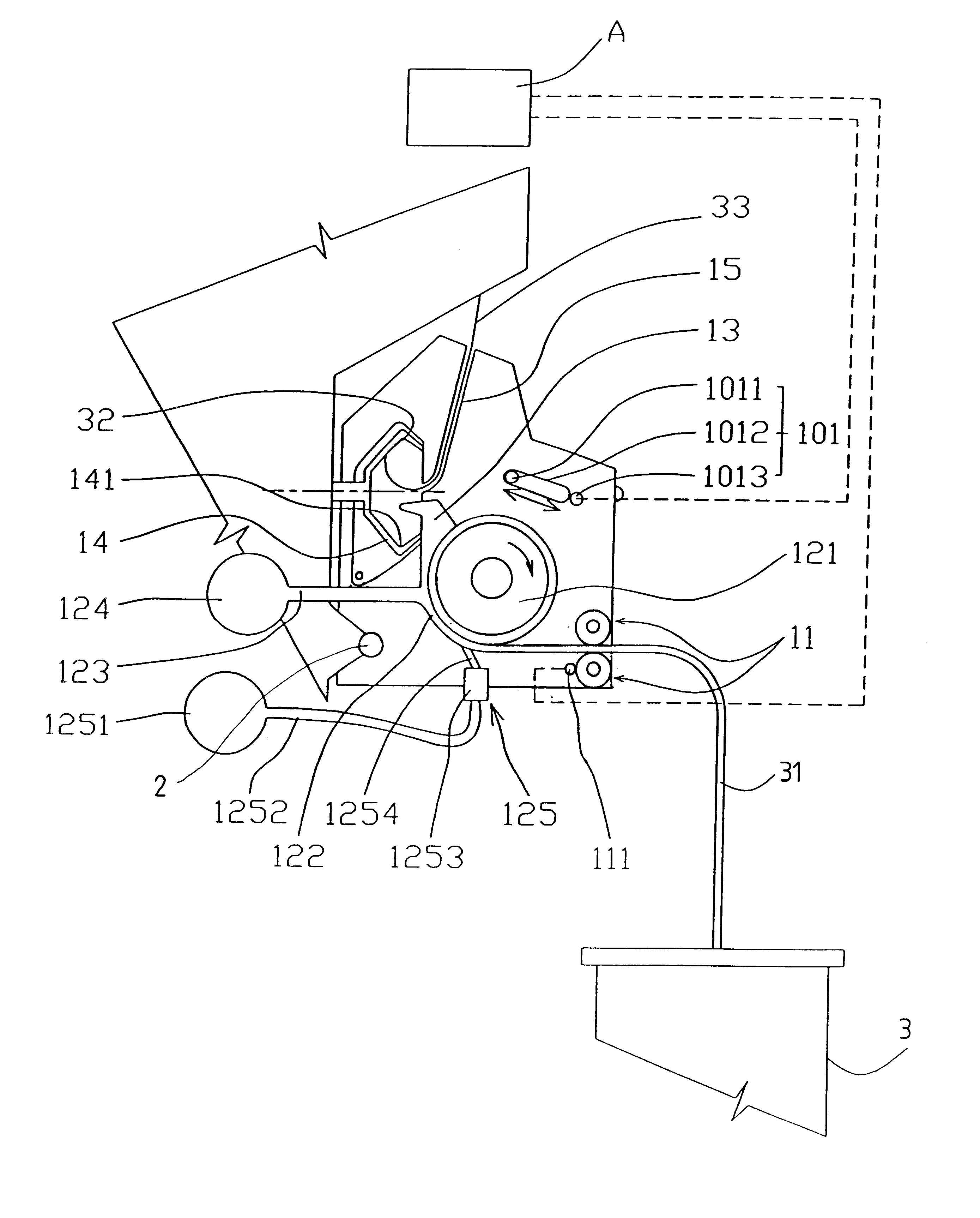
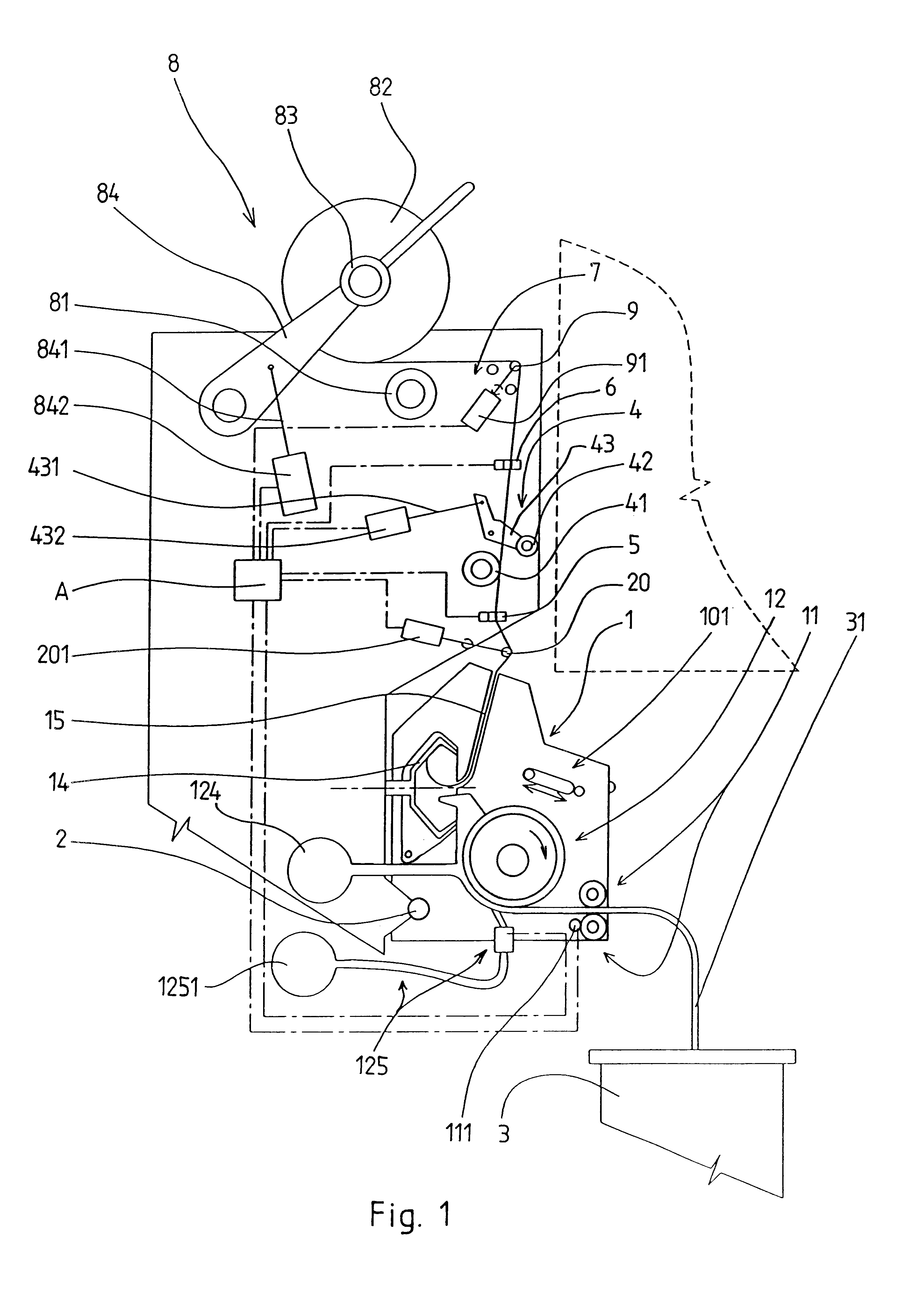
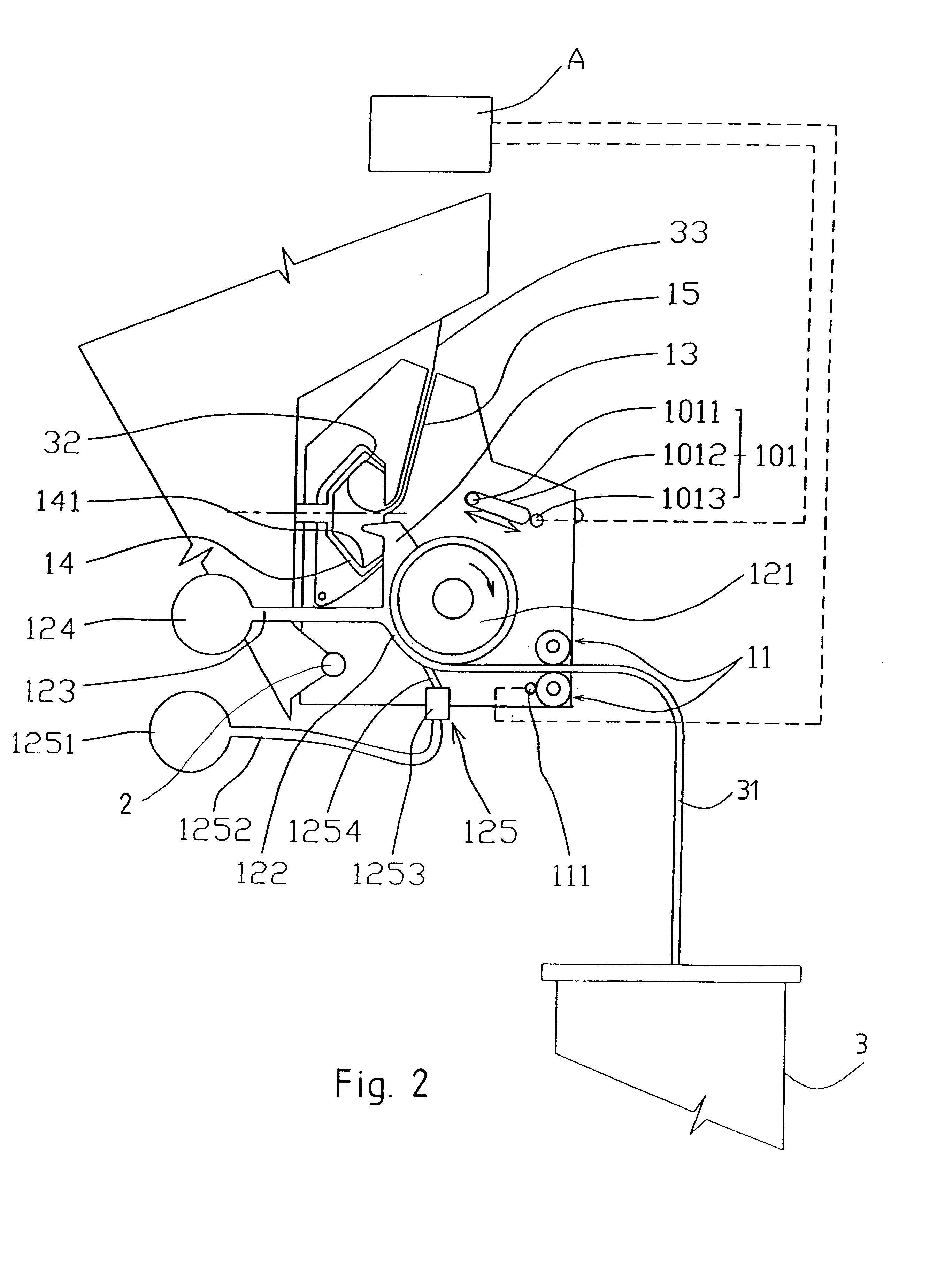
The rotor spinning machine comprises a number of operating units arranged next to each other, each of which produces yarn from a textile fibre sliver and winds the produced yarn on a bobbin. The rotor spinning machine can be fully automated or semi-automatic or manually attended.

A fully automated rotor spinning machine is fitted with an attending device seated and adapted to travel along the operating units of the rotor spinning machine and fitted with means for carrying out attending operations on the operating unit in resuming the spinning and / or doffing wound bobbins and replacing them by empty tubes.

A semi-automatic rotor spinning machine is partly attended manually, partly fitted with means for spinning-in automation used to carry out final spinning-in steps.

Each operating unit of a semi-automatic rotor spinning machine comprises a spinning unit 1 mounted and adapted to pivot in a well-known manner on a pin 2 mounted in the machine frame. A can 3 with sliver 31 ...


PUM

PropertyMeasurementUnit
lengthaaaaaaaaaa
timeaaaaaaaaaa
sizeaaaaaaaaaa

Abstract

A method of spinning-in yarn on an operating unit of a rotor spinning machine includes steps of yarn preparation for spinning-in, steps of spinning rotor preparation for spinning-in, and final spinning-in steps. The final spinning-in steps include at least the beginning of the sliver supply to the singling-out device, leading of the fibers from the singling-out device away from the spinning rotor for a predetermined time interval, letting the spinning-in yarn end get into contact with the collecting groove of the spinning rotor, and starting of the yarn draw-off and winding. At least some final spinning-in steps are time synchronized in relation to the closing of the spinning unit thus obtaining optimum piecer quality repeatedly at all operating units of the machine.

Description

The invention relates to a method of spinning-in yarn on an operating unit of a rotor spinning machine which comprises steps of yarn preparation for spinning-in, steps of spinning rotor preparation for spinning-in, and final spinning-in steps. The steps of yarn preparation for spinning-in comprise at least the detection of the yarn end on the bobbin or the preparation of auxiliary yarn when spinning-in on an empty tube, unwinding and metering a yarn length required for spinning-in, setting the yarn into its spinning-in position on the operating unit of the rotor spinning machine in which the yarn is outside the reach of the yarn distributor and not clamped between the rollers of the draw-off mechanism, creating the spinning-in yarn end and introducing it into the yarn delivery tube from the spinning rotor. The step of the spinning rotor preparation for the spinning-in comprise at least the opening of the spinning unit, cleaning of the spinning rotor, closing of the spinning unit. Th...

Claims


Application Information

Patent Timeline
Patent Type & Authority Patents(United States)
IPC IPC(8): D01H4/00D01H4/50D01H4/48
CPCD01H4/50
Inventor LUDVICEK, JOSEFKOUSALIK, PAVELMARKL, JAROSLAVTESAR, TOMAS
Owner RIETER CZ AS
Why Eureka
Try Eureka