Perforation blade for forming a burst-resistant easy-open corner in a heavy duty bag

a perforation blade and heavy-duty technology, applied in the field of heavy-duty plastic bags, can solve the problems of inability to manually open the bag by hand, substantial physical effort, inadvertent uncontrolled dumping or over-dumping of contents, etc., and achieve the effect of improving the perforation blad

Inactive Publication Date: 2003-08-26
EXOPACK TECH
View PDF7 Cites 58 Cited by
  • Summary
  • Abstract
  • Description
  • Claims
  • Application Information

AI Technical Summary

Benefits of technology

to provide a bag cutting device which includes an improved perforation blade used to form an easy-open corner.
These and other objects of the present invention are achieved in the preferred embodiments disclosed below by providing a perforation blade used for cutting a perforated tear line in a bag to form an easy-open corner portion. The corner portion is removable to define a pourer through which contents of the bag are dispensed. The bag has first and second walls with joined opposing side edges, opposing end edges, and a seal line proximate one of the end edges for sealing closed an end of the bag. The perforation blade includes a base formed to span the corner portion of the bag. The base has a first end adapted to extend to the end edge of the bag proximate the seal line, and a second end adapted to extend to one side edge of the bag. A series of specifically spaced perforation teeth are formed with the base, and are adapted to penetrate the first and second walls of the bag to form a corresponding series of perforations at the corner portion of the bag. A starter tooth is formed at the first end of the base, and is adapted to cut a starter nick in a skirt of the bag between the end edge and the proximate seal line. A burst protection gap is formed between the starter tooth and a first of the series of perforation teeth. The burst protection gap is adapted for safely receiving the seal line of the bag to prevent severing the seal line when cutting the perforations.
In another embodiment, the invention is a bag cutting device with a perforation blade used for cutting a perforated tear line in a bag to form an easy-open corner portion. The perforation blade includes a base formed to span the corner portion of the bag. The base has a first end adapted to extend to the end edge of the bag proximate a seal line, and a second end adapted to extend to one side edge of the bag. A series of closely spaced perforation teeth are formed with the base, and are adapted to penetrate the first and second walls of the bag to form a corresponding series of perforations at the corner portion of the bag. A starter tooth is formed at the first end of the base, and is adapted to cut a starter nick in a skirt of the bag between the end edge and the proximate seal line. A burst protection gap is formed between the starter tooth and a first of the series of perforation teeth. The burst protection gap is adapted for safely receiving the seal line of the bag to prevent severing the seal line when cutting the perforations.
As best shown in FIG. 3, the blade 10 includes an enlarged starter tooth 51 integrally formed with the base 10A and spaced apart from a first one 52 of the perforation teeth 10B. The last of the perforation teeth 10B is formed at the opposite end of the base 10A. Preferably, the teeth 10B are uniformly spaced and are identical in both length and width. When cutting perforations in the bag 20, the starter tooth 51 penetrates the walls 21 and 22 of the bag 20 and forms a starter nick 54 in the skirt 55 between the end edge 25 and seal line 28. Simultaneously, the perforation teeth 10B penetrate the bag walls 21 and 22 and form the perforated tear line 30 extending from the seal line 28 to the near side edge 23 of the bag 20. The distance between the starter tooth 51 and first perforation tooth 52 defines a relatively deep, burst protection gap 56. The gap 56 is formed to safely receive the seal line 28 of the bag 20 during cutting to prevent the seal line 28 from being severed or otherwise damaged, thereby reducing the likelihood of the bag 20 bursting during shipping and handling. Preferably, the burst protection gap 56 is approximately 20-25 percent deeper than the space 58 formed between adjacent perforation teeth 10B.
As shown in FIG. 4, the bag 20 is opened by gripping the top end edge 25 and pulling the bag apart on opposite sides of the tear line 30. A progressive tearing motion readily begins at the starter nick 54 formed on the skirt 55 of the bag 20 and extends along the tear line 30 into the vertical segment 30A causing the lands between the perforations to rupture. The tear extends through the uncut seal line 28 down the vertical segment 30A and then into the first arcuate transition segment 30B. Because of the curved pattern of perforations in the arcuate transition segment 30B, the tear easily transitions into the diagonal segment 30C with relatively little added physical effort, and without deviating from the predetermined path defined by the tear line 30. From the first transition segment 30B, the tear extends at an incline along the diagonal segment 30C to the second arcuate transition segment 30D; and finally, along the short horizontal segment 30E to the side edge 23 of the bag 20. The corner portion 32 is thus completely severed from the bag 20. A pourer is formed in the corner of the bag 20 through which the contents can be dispensed. Contents can be dispensed with complete visibility and without diverting the flow of material, because the bag material severed to form the opening is completely removed and discarded.

Problems solved by technology

In the absence of a cutting knife or tool, attempts to manually tear open the bag by hand are often futile, because of the relative thickness and durability of such bags.
In many cases, this requires substantial physical effort, and sometimes results in inadvertent uncontrolled dumping or over-dumping of the contents.
While such bags solve many problems of the prior art, certain disadvantages and limitations remain.
Since the perforations formed at the corner of the bag typically pass entirely, or at least partially, through the end seal, the bag is prone to inadvertent rupture and spillage during transport and handling.

Method used


Image

  • Perforation blade for forming a burst-resistant easy-open corner in a heavy duty bag
  • Perforation blade for forming a burst-resistant easy-open corner in a heavy duty bag
  • Perforation blade for forming a burst-resistant easy-open corner in a heavy duty bag

Examples


Embodiment Construction

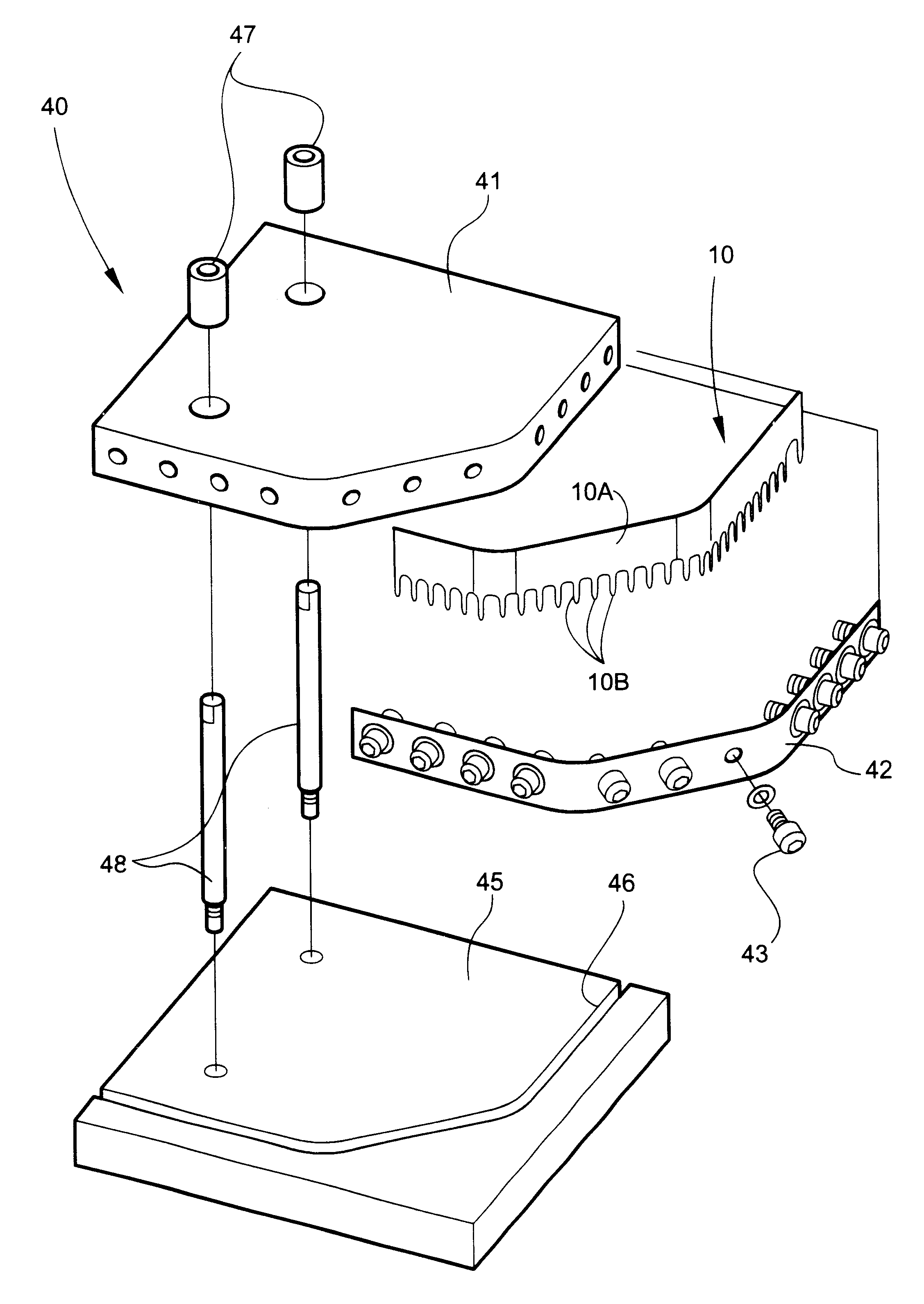
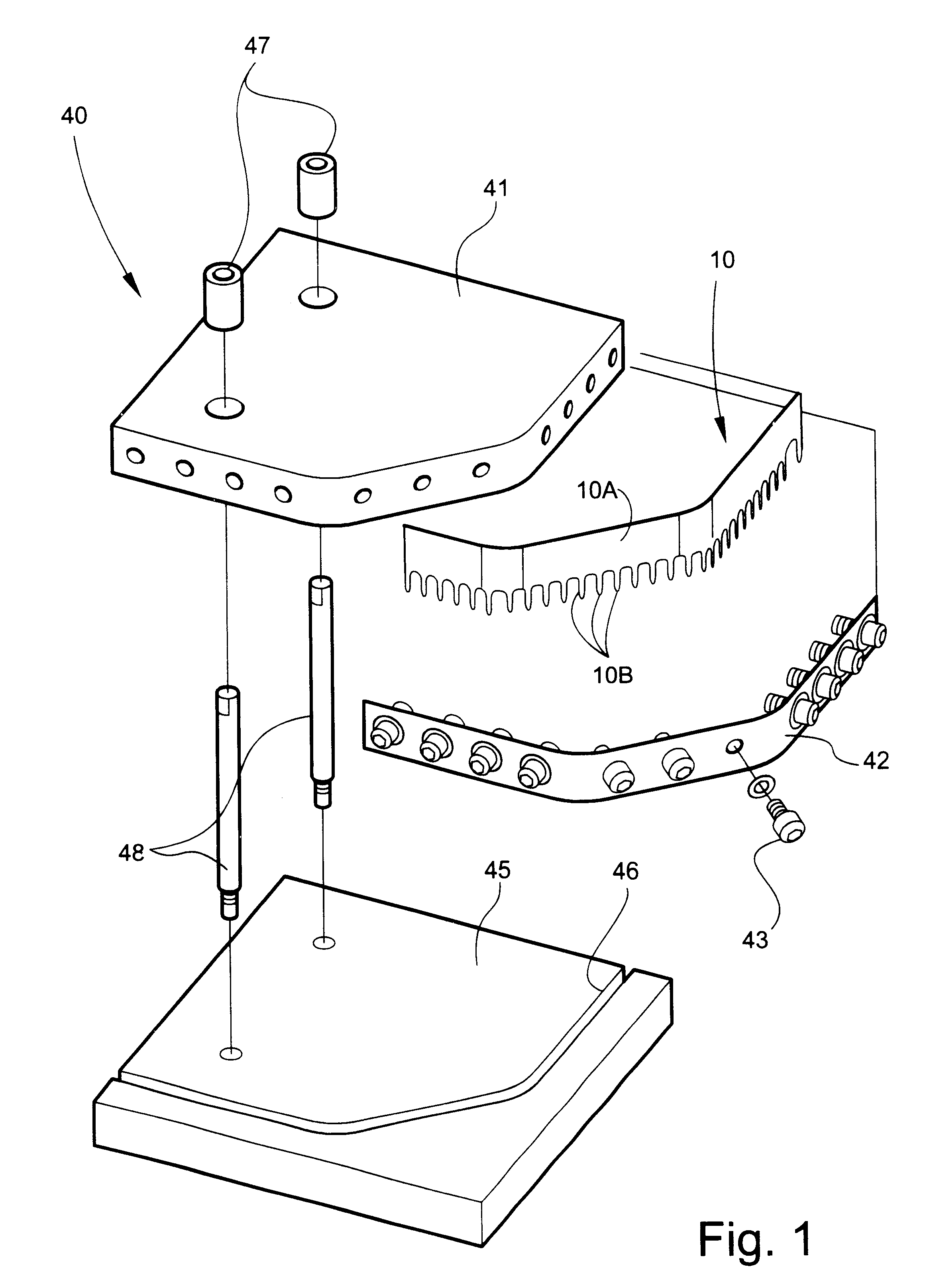
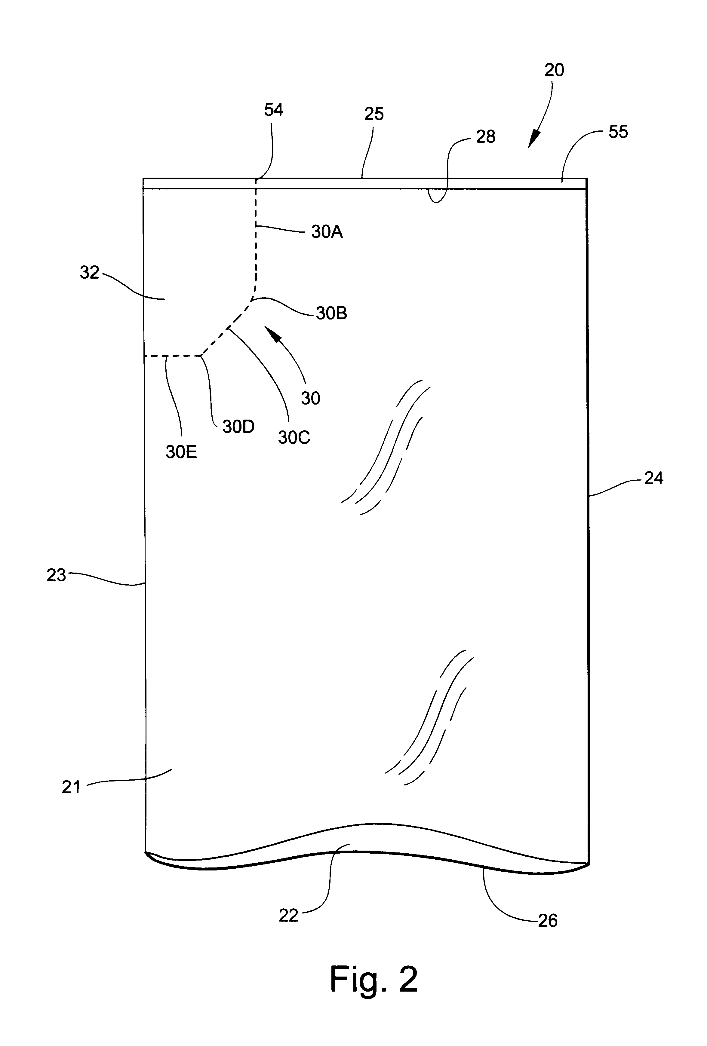
Referring now specifically to the drawings, a perforation blade used to form a bag with an easy-open corner is illustrated in FIG. 1 and shown generally at reference numeral 10. Such bags are typically fabricated from polyolefin sheet or tube stock, and are commonly used for heavy-duty applications such as for transport, sale, and storage of materials such as chemicals, salt, fertilizer, lawn lime, potting soil, and the like. The bag 20, shown in FIG. 2, has first and second walls 21 and 22 with joined opposing side edges 23 and 24, opposing end edges 25 and 26, and a seal line 28 proximate the end edge 25 for sealing closed an end of the bag 20. The opposite end of the bag 20 remains open for filling. The term "joined" is used in a broad sense to mean either two formerly separate sheets connected together, or integrally formed by, for example, folding over a sheet to define an edge. The perforation blade 10 forms a line of closely-spaced perforations 30 in each of the bag walls 21 ...


PUM

PropertyMeasurementUnit
thicknessaaaaaaaaaa
widthaaaaaaaaaa
widthaaaaaaaaaa

Abstract

A perforation blade is used for cutting a perforated tear line in a bag to form an easy-open corner portion. The perforation blade includes a base formed to span the corner portion of the bag. The base has a first end adapted to extend to the end edge of the bag proximate a seal line, and a second end adapted to extend to one side edge of the bag. A series of closely spaced perforation teeth are formed with the base, and are adapted to penetrate the first and second walls of the bag to form a corresponding series of perforations at the corner portion of the bag. A starter tooth is formed at the first end of the base, and is adapted to cut a starter nick in a skirt of the bag between the end edge and the proximate seal line. A burst protection gap is formed between the starter tooth and a first of the series of perforation teeth. The burst protection gap is adapted for safely receiving the seal line of the bag to prevent severing the seal line when cutting the perforations.

Description

TECHNICAL FIELD AND BACKGROUND OF THE INVENTIONThis invention relates generally to heavy duty plastic bags, and more specifically, to a perforation blade used to form an easy-open corner which resists inadvertent bursting during handling of a filled bag. Such bags are commonly used for heavy-duty applications, such as for transport, sale, and storage of materials such as chemicals, salt, fertilizer, lawn lime, potting soil, and the like. The are typically fabricated from LD, HD, or LLD polyolefin sheet or tube stock, such as polyethylene or polypropylene having a thickness in the range of 3 to 12 mils. The sheet or tube stock may be coextruded or monoextruded, and may be a single ply or multi-ply material. The multi-ply material may be multiple thicknesses of the same sheet or tube stock, or different materials to provide particular characteristics, such as strength, flexibility, UV resistance, or color. The sheet stock may also be woven or non-woven synthetic or non-synthetic mater...

Claims


Application Information

Patent Timeline
Patent Type & Authority Patents(United States)
IPC IPC(8): B31B19/20B31B19/00B26F1/00B26F1/18B26F1/22B65D33/36
CPCB26F1/18B26F1/22B31B19/20B31B2219/147B31B70/20Y10T83/9319
Inventor ALBRIGHT, TIMOTHY L.
Owner EXOPACK TECH
Why Eureka
Try Eureka