Micro-fluid test card

A test card and microfluidic technology, applied in the direction of analyzing materials, instruments, etc., can solve the problems of not being able to avoid storage liquid well, complex structure, and liquid flow rate that cannot be controlled according to user needs.

Inactive Publication Date: 2016-08-17
DONGGUAN BOSH BIOTECHNOLOGIES LTD
View PDF6 Cites 4 Cited by
  • Summary
  • Abstract
  • Description
  • Claims
  • Application Information

AI Technical Summary

Problems solved by technology

[0009] The technical problem to be solved by the present invention is to provide a microfluidic test card to solve the problems in the prior art that the structure is relatively complex, which is not conducive to production and assembly; the liquid flow rate cannot be controlled according to the user's needs; and the storage liquid cannot be well avoided.

Method used


Image

  • Micro-fluid test card
  • Micro-fluid test card
  • Micro-fluid test card

Examples


Embodiment 1

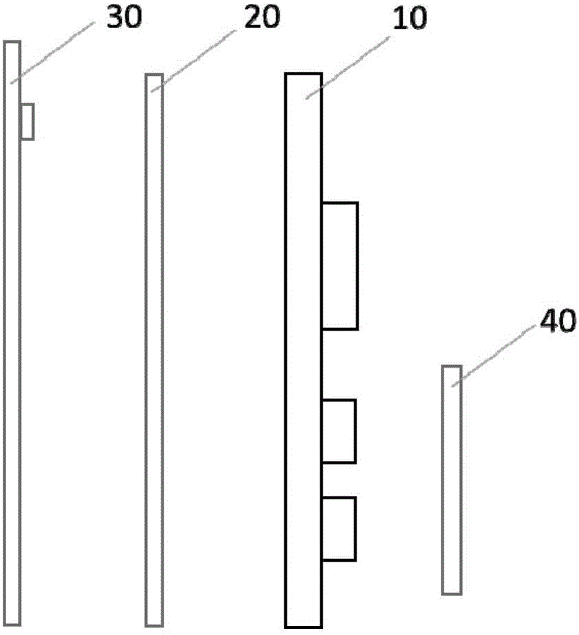
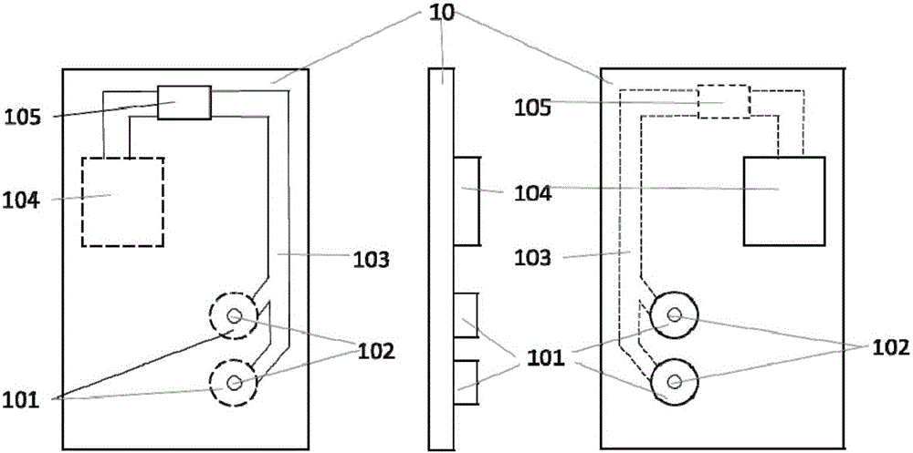
[0056] Such as Figure 2 to Figure 4 As shown, the present invention discloses a microfluidic test card, the test card includes a reaction chamber and a microchannel layer 10, a microchannel sealing layer 20 and a detection layer 30; the microfluidic test card further includes: At least one liquid storage chamber and pump chamber 101 of the microchannel layer 10; the first liquid storage chamber sealing layer for sealing the liquid storage chamber and pump chamber 101 and isolating the microchannel 103 that can be communicated; located in the first liquid storage chamber The opposite side of the sealing layer is used to seal the second liquid storage sealing layer of the liquid storage chamber and the pump chamber 101; the waste liquid pool 104 is convex in the reaction chamber and the microchannel layer 10 and communicates with the reaction chamber 105; Second, the pump chamber sealing layer 40 outside the liquid storage sealing layer. The microchannel 103 and the reaction c...

Embodiment 2

[0062] Such as Figure 6 As shown, the present invention discloses a microfluidic test card, which includes a reaction chamber and a microchannel layer 50, a microchannel sealing layer and a detection layer; the microfluidic test card further includes: protruding from the reaction chamber and microchannel At least one liquid storage chamber and pump chamber 60 of layer 50; the first liquid storage chamber sealing layer for sealing the liquid storage chamber and pump chamber 60 and isolating the microchannel that can be communicated; The side is used to seal the second liquid storage sealing layer of the liquid storage chamber and the pump chamber 60; the waste liquid pool 501 protrudes from the reaction chamber and the microchannel layer 50 and communicates with the reaction chamber; and, located in the second liquid storage seal Layer outside the pump chamber seal layer. The microchannel and the reaction chamber are located on the same side of the reaction chamber and the mi...

Embodiment 3

[0069] Such as Figure 7 As shown, the present invention discloses a microfluidic test card, which includes a reaction chamber and a microchannel layer 70, a microchannel sealing layer 80 and a detection layer 90; the microfluidic test card further includes: At least one liquid storage chamber and pump chamber 701 of the microchannel layer 70; the first liquid storage chamber sealing layer for sealing the liquid storage chamber and pump chamber 701 and isolating the microchannel that can be communicated; The opposite side of the layer is used to seal the second liquid storage sealing layer of the liquid storage chamber and the pump chamber 701; the waste liquid pool is protruding from the reaction chamber and the microchannel layer 70 and communicated with the reaction chamber; and, located in the second liquid storage The pump chamber sealing layer 85 outside the sealing layer. The microchannel and the reaction chamber are positioned on the same side of the reaction chamber ...


PUM


Abstract

The invention discloses a microfluidic test card, which includes a reaction chamber and a microchannel layer, a microchannel sealing layer and a detection layer, and the microfluidic test card further includes: at least one Liquid storage chamber and pump chamber; each liquid storage chamber and pump chamber and the first liquid storage chamber sealing layer used to isolate the liquid storage chamber and pump chamber between the connected microchannels; and the waste liquid pool, which protrudes from the reaction chamber Cum the microchannel layer and communicate with the reaction chamber. The technical scheme of the invention can greatly reduce the volatility of the liquid, thereby prolonging the storage time of the test card and reducing the loss of the test card.

Description

technical field [0001] The invention relates to microfluidic biological detection, in particular to a microfluidic test card which can be assembled freely, can freely control the flow rate of reaction liquid, and prevent storage liquid from leaking out. Background technique [0002] Due to the development of microfluidic technology using micro-solutions, the use of laboratory-on-a-chip (LOC) or microfluidic chips is proud to break away from the shackles of traditional research experiments, and move further towards commercial applications with more practical value. In the fields of chemistry and biology, microfluidic systems are used more and more, such as the transmission of microfluids, the synthesis of quantitative compounds, sample separation, component analysis and chemical reactions. [0003] At present, microfluidic chips are mainly electrophoresis chips, and the injection of reaction reagents is realized by electrophoresis and electroosmosis. Although the purpose of m...

Claims


Application Information

Patent Timeline
Patent Type & Authority Applications(China)
IPC IPC(8): G01N35/00
CPCG01N35/00
Inventor 唐金平汪明华石西增
Owner DONGGUAN BOSH BIOTECHNOLOGIES LTD
Why Eureka
Try Eureka