Illumination system with reduced heat load

Inactive Publication Date: 2003-08-26
CARL ZEISS SEMICON MFG
View PDF9 Cites 14 Cited by
  • Summary
  • Abstract
  • Description
  • Claims
  • Application Information

AI Technical Summary

Benefits of technology

The object is solved according to the invention for an illumination system for wavelengths .ltoreq.193 nm, particularly for EUV lithography, in that the heat load is reduced by shifting the raster elements of the second mirror or of the second lens out of the focus of the light bundles of the raster elements of the first mirror or first lens with raster elements. Due to the divergence of the light bundles, a light bundle becomes broader with increasing distance from the focal point or from the image position of the secondary light source.
By changing the points of incidence of the light channels passing through from the light source to the exit pupil, in a preferred embodiment, a specified illumination can be established in the exit pupil. Any desired distribution can be produced by such an adjustment of the light distribution in the exit pupil, and light losses, which occur, for example, when diaphragms are used for solving this problem, are avoided.

Problems solved by technology

A disadvantage of the system known from DE 199 03,807 is that with field raster 5 elements, a light source with a diameter X is imaged directly into a pupil raster element.

Method used


Image

  • Illumination system with reduced heat load
  • Illumination system with reduced heat load
  • Illumination system with reduced heat load

Examples


Embodiment Construction

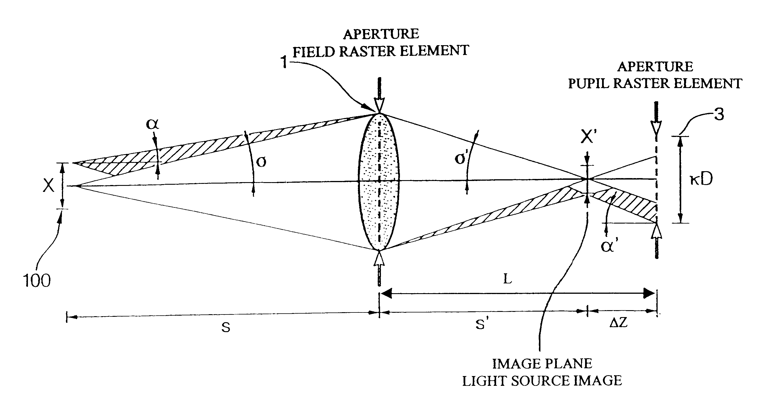
A schematic drawing showing the principal components for deriving the formulas for defocusing by changing the refractive power of the first raster elements is shown in FIG. 1. As is shown in FIG. 1, the first raster elements have a positive optical power, thus providing a convergent light bundle with a focal point in the plane of the images of the light sources. FIG. 1 is shown in refractive representation. A person skilled in the art can transfer the parameters to the reflective optics necessary for exposure systems with wavelengths .ltoreq.193 nm, particularly for EUV lithograpy, without inventive activity.

The principle components of the system shown in FIG. 1 include a light source 100, a first raster element, e.g., field raster element 1, and a second raster element, e.g., pupil raster element 3. If light source 100 has a diameter X, and if pupil raster element 3 has a diameter D and is filled with illumination to a ratio .kappa., then the distance between field raster element 1...


PUM

PropertyMeasurementUnit
wavelengthsaaaaaaaaaa

Abstract

An illumination system for wavelengths <=193 run comprises (a) a first raster element upon which a light bundle emitted from a light source impinges, for producing a convergent light bundle having a focal point, and (b) a second raster element. The convergent light bundle impinges on the second raster element outside the focal point. There is also provided an illumination system for wavelengths <=193 nm, comprising (a) a first plurality of raster elements upon which a light bundle emitted from a light source impinges, for producing a plurality of convergent light bundles, where a member of the first plurality of raster elements produces a member of the plurality of convergent light bundles having a focal point, and (b) a second plurality of raster elements. The member of the plurality of convergent light bundles impinges on a member of the second plurality of raster elements outside the focal point.

Description

1. Field of the InventionThe present invention relates to an illumination system, and more particularly an illumination system for wavelengths .ltoreq.193 nm, such as that used for EUV lithography. The invention also relates to a method for reducing heat load, and a projection exposure apparatus comprising such an illumination system.2. Description of the Prior ArtIn order to be able to further reduce the line widths for electronic components, particularly in the submicron region, it is necessary to reduce the wavelengths of the light utilized for microlithograpy. With wavelengths smaller than 193 nm, for example, lithograpy with soft x-rays, so-called EUV lithography, is possible.An illumination system suitable for EUV lithography should homogeneously, i.e., uniformly, illuminate a field used in EUV-lithography, particularly a ring field of an objective, with as few reflections as possible. Furthermore, a pupil of the objective will be illuminated independently of the field up to a...

Claims


Application Information

Patent Timeline
Patent Type & Authority Patents(United States)
IPC IPC(8): G03F7/20G21K1/00G21K1/06G21K5/04G02B17/00G02B19/00H01L21/027
CPCG03F7/70083G03F7/702G03F7/70233G03F7/70358G03F7/70891G03F7/70983G21K1/06G21K5/04
Inventor SINGER, WOLFGANGULRICH, WILHELMANTONI, MARTIN
Owner CARL ZEISS SEMICON MFG
Why Eureka
Try Eureka