ROV-deployable subsea wellhead protector

Inactive Publication Date: 2003-09-09
ARNING MICHAEL DEAN
View PDF23 Cites 42 Cited by
  • Summary
  • Abstract
  • Description
  • Claims
  • Application Information

AI Technical Summary

Problems solved by technology

Exploratory wells drilled in deeper waters are often simply plugged and abandoned.
However, while such plugs effectively isolate the wellbore from the environment, the subsea wellhead, which rests on and protrudes above the sea floor, is left exposed and unprotected.
Possible sources of damage include corrosion from the immersion in sea water; objects falling onto the subsea wellhead and scarring the various surfaces; or damage by objects falling on or otherwise striking the wellhead, such as boat anchors and the like.
While such protectors may be effective, their great weight requires that they be run using the drilling rig to lower the protector in place, usually on a string of drill pipe.
This requirement means that expensive rig time must be devoted to the placement of metal protectors.

Method used


Image

  • ROV-deployable subsea wellhead protector
  • ROV-deployable subsea wellhead protector
  • ROV-deployable subsea wellhead protector

Examples


Embodiment Construction

While various embodiments within the scope of the present invention will be apparent to those skilled in the art, with reference to the figures some of the presently preferred embodiments are described.

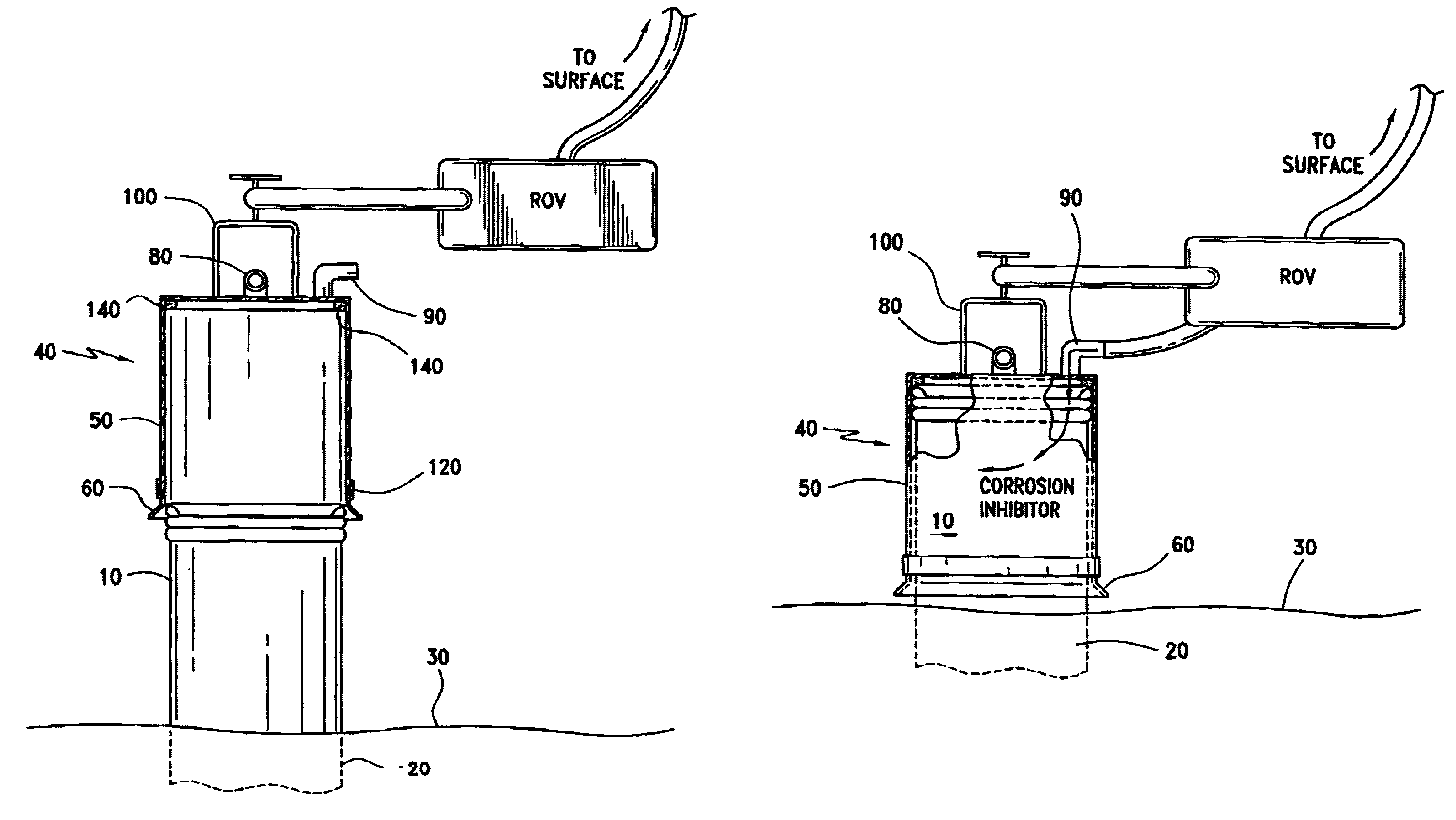
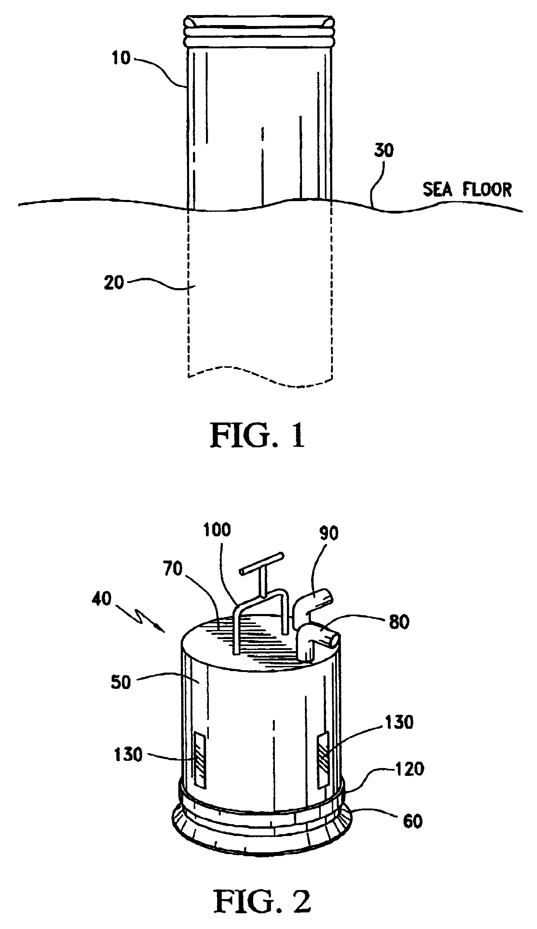
FIG. 1 shows a typical subsea wellhead arrangement. Subsea wellhead 10 sits atop a casing string 20 which is cemented in a subterranean borehole. Subsea wellhead 10 is usually in relatively close proximity to sea floor 30. A support mat may be in place to provide additional stability and bearing surface against sea floor 30. The wellhead typically has multiple sealing and connector surfaces which must be protected.

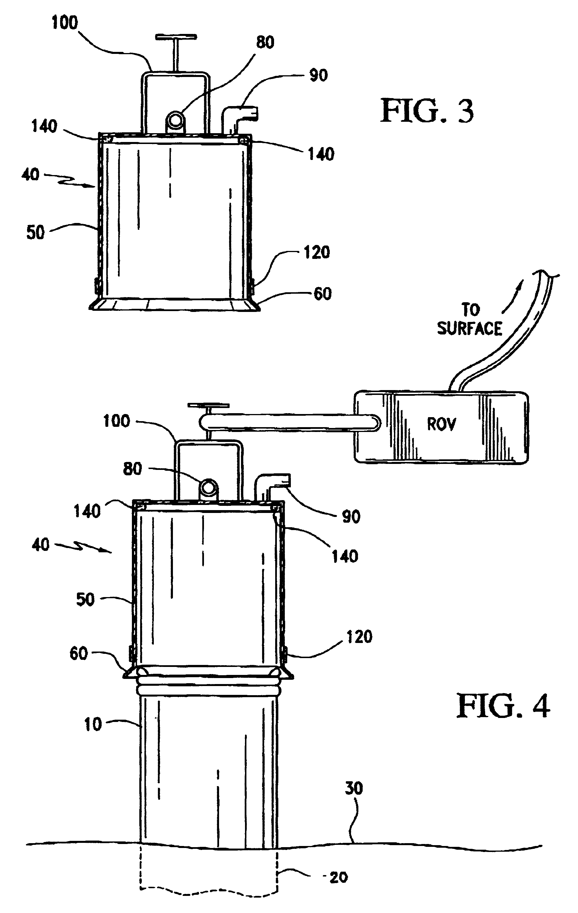
FIGS. 2 and 3 show various views of protector 40. FIG. 2 is a perspective view of protector 40. FIG. 3 is a view in partial cross section. Protector 40 comprises a hollow cylindrical main body 50, preferably with an outwardly flaring circumferential skirt 60 around an open end. A cover 70 encloses the other end of main body 50. A vent 80 provides hydraulic communication thro...


PUM


Abstract

A protector for placement over subsea wellheads. A main body is cylindrical, with an inner diameter of sufficiant size to fit over a subsea wellhead. One end of the main body has a cap across it. A vent and a pump-through port, which permits pumping in of corrosion inhibitors, is in the cap. The open end of the main body has an outwardly flaring skirt to help guide the protector into place over the wellhead. The main body is formed from polyurethane via molding or other suitable methods.

Description

BACKGROUND - FIELD OF ARTThis invention relates to apparatus used in offshore oil and gas operations. With more specificity, this invention relates to apparatus for the protection of the subsea wellheads of offshore wells.BACKGROUND - RELATED ARTIn relatively shallow offshore waters, wells are drilled from bottom-supported drilling rigs such as jackup rigs. When such wells are completed, the completion can often be carried out by a surface wellhead mounted on some sort of production structure, for example a standalone well caisson. The wellhead equipment for such wells is very similar to equipment on onshore wells or platform wells.In deeper waters, however, wells must be drilled with floating drilling rigs such as semi-submersibles and drill ships. Exploratory wells drilled in deeper waters are often simply plugged and abandoned. However, current technology permits many of such wells to be "salvaged" in the sense that the wells are eventually completed and tied back to a production...

Claims


Application Information

Patent Timeline
IPC IPC(8): E21B33/037E21B33/03
CPCE21B33/037
Inventor LAY, JR., MILFORDLANDRY, GREGORY J.
Owner ARNING MICHAEL DEAN
Why Eureka
Try Eureka