Printer device

a printing device and printing technology, applied in the direction of printed circuit details, printed circuit structure associations, instruments, etc., can solve the problems of inability to design fully compact printer devices, inability to meet users who want a portable printing device, and inability to use radiation plated in the related ar

Inactive Publication Date: 2003-09-09
OLYMPUS OPTICAL CO LTD
View PDF8 Cites 10 Cited by
  • Summary
  • Abstract
  • Description
  • Claims
  • Application Information

AI Technical Summary

Benefits of technology

According to the present invention, the control printed-circuit board including the control circuit that controls at least one of paper feed and ink ribbon feed is placed on the bottom of the printer device. The power printed-circuit board including the charge circuit is located along one side surface of the printer device. The charge circuit charges the rechargeable battery brou...

Problems solved by technology

Besides, a radiating plated employed in the related art becomes unnecessary.
This poses a problem in that the printer device ca...

Method used


Image

  • Printer device
  • Printer device
  • Printer device

Examples


Embodiment Construction

An embodiment of the present invention will be described with reference to the drawings below.

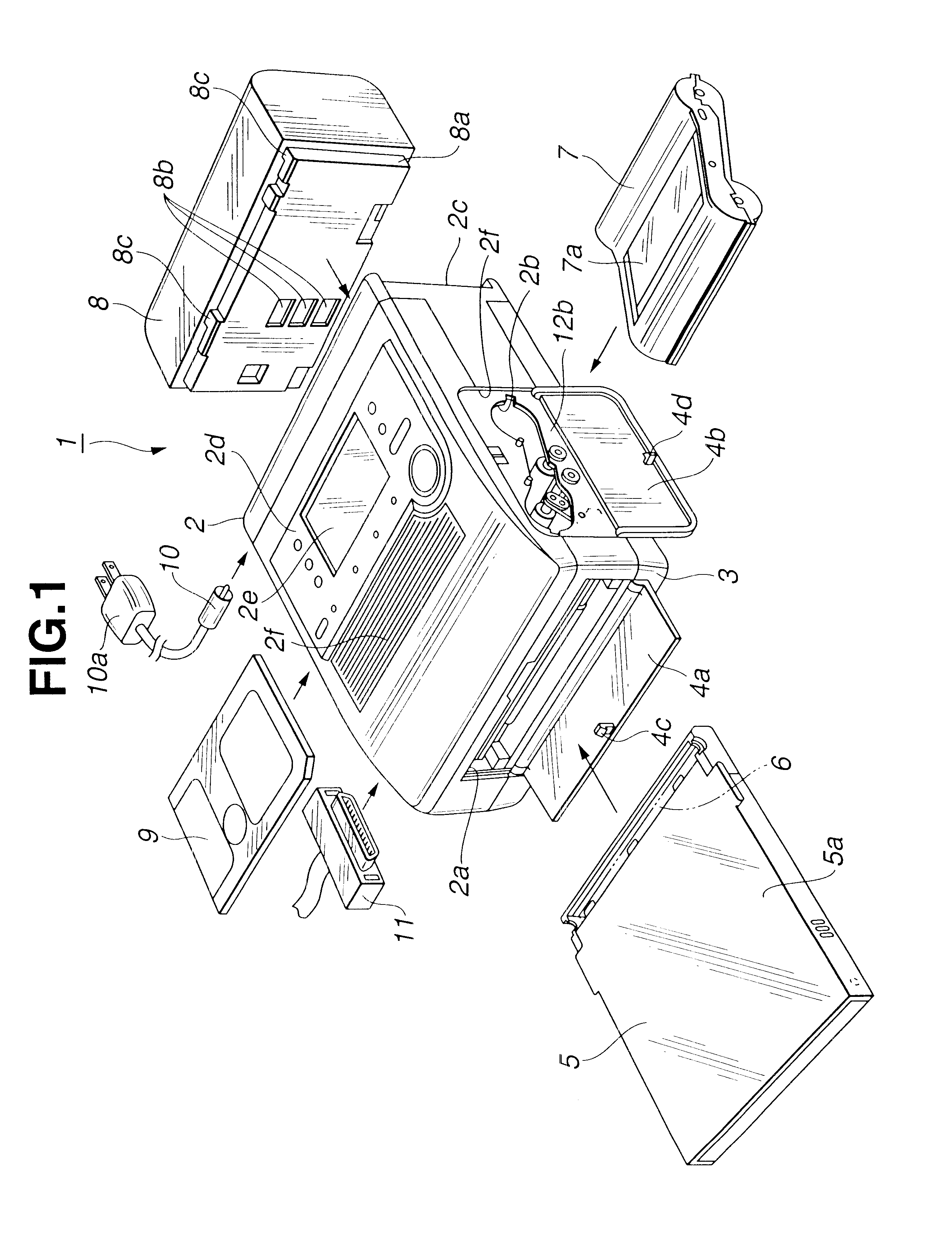
FIG. 1 is a perspective view showing the overall configuration of a printer device in accordance with an embodiment of the present invention.

As shown in FIG. 1, the housing of a printer device 1 in accordance with the present embodiment consists of a body cover 2 and a body bottom 3. The body cover 2 encloses various mechanisms, components, and printed-circuit boards that are necessary for printing. The body bottom 3 is attached to the lower part of the body cover 2.

A paper feed cassette loading opening 2a through which a paper feed cassette 5 is loaded is formed in the front surface of the body cover 2 of the device 1 (left forward part of the drawing). A plurality of sheets of recording paper 6 can be stowed in the paper feed cassette loading opening 2a so that it can be unloaded freely.

Moreover, an open / close lid 4a capable of being opened and closed is shown in an open position on the b...


PUM


Abstract

A compact and lightweight design for a printer device that is optimally portable. A printed circuit board assembly 22 incorporated in the printer device includes a control printed-circuit board 22a and a power printed-circuit board 22b arranged substantially in L-shaped fashion. A connector 23 electrically couples boards 22a and 22b to each other. The power printed-circuit board, on which large current flows, is located near a large current source. A charge circuit, battery contacts and a control circuit for applying voltage to a thermal head are mounted and concentrated on the sole power printed-circuit board. The control printed-circuit board 22a for controlling recording paper and ink ribbon feed, which require only small current, is located near a small current source, such as an actuator needed for feeding recording paper and an ink ribbon including a recording paper/ribbon feeding mechanism 17. The circuits for controlling recording paper feed and ink ribbon feed are mounted and concentrated on the sole control printed-circuit board 22a. The substantially L-shaped printed-circuit board assembly, serving as a motherboard, is incorporated in the printer device to realize the capabilities of the printer device.

Description

This application claims benefit of Japanese Application No. 2000-69928 filed in Japan on Mar. 14, 2000, the contents of which are incorporated by this reference.BACKGROUND OF THE INVENTION1. Field of the InventionThe present invention relates to a printer device, or more particularly, to a printer device that is so compact and lightweight as to be portable.2. Description of Related ArtPersonal computers and video recorders have been popular in recent years. Various types of printer devices capable of recording images produced by equipment including the personal computer and video recorder have been proposed, and the needs for printer devices have increased. There is therefore an increasing demand for a printer device that is inexpensive and capable of producing high-definition print images. Moreover, a portable printer device that is compact and lightweight is highly demanded along with the needs for a mobile printer device that permits printing at any time in any place.In a typical...

Claims


Application Information

Patent Timeline
IPC IPC(8): B41J17/07B41J11/42B41J17/02H05K1/14
CPCB41J11/42B41J17/07H05K1/14
Inventor ISHIKAWA, KAZUHIDE
Owner OLYMPUS OPTICAL CO LTD
Why Eureka
Try Eureka