Road/air vehicle

a technology for air vehicles and roads, applied in the direction of aircraft convertible vehicles, transportation and packaging, retractable wheels, etc., can solve the problems of no commercial success or particularly practical success of aircraft, and the vehicle is impractical in either environment, and the success of the test is limited

Inactive Publication Date: 2003-09-16
HAYNES ROBIN
View PDF28 Cites 74 Cited by
  • Summary
  • Abstract
  • Description
  • Claims
  • Application Information

AI Technical Summary

Benefits of technology

Accordingly it is a principal object of the invention to provide an improved road/air vehicle having jet thrust power for flight operations and discreet torque power for ground operations. It is another object of the invention to provide an improved road/air vehicle having two symmetrically lateral flight surfaces, comprising a canard wing plus a main wing with tip fin stabilizers. It is another object of the invention to provide an improved road/air vehicle inclu...

Problems solved by technology

Some of these attempts have met with limited success, in two cases the machines have been type certified by the Civil Aeronautics Agency (now the Federal Aviation Administration) as production aircraft.
However, none of these craft have been commercially successful or particularly practical.
The design requirements of a ground vehicle are entirely different to those of an airplane and the result of trying to marry the two together into one craft has hitherto been to produce a vehicle which is impractical in either environment.
One design, Pat. No. 4,269,374--Miller, has flight surfaces that all fold within the body, however the method of folding and the choice of conventional empennage design result in an aircraft with insufficient wing area and ...

Method used


Image

  • Road/air vehicle
  • Road/air vehicle
  • Road/air vehicle

Examples


Embodiment Construction

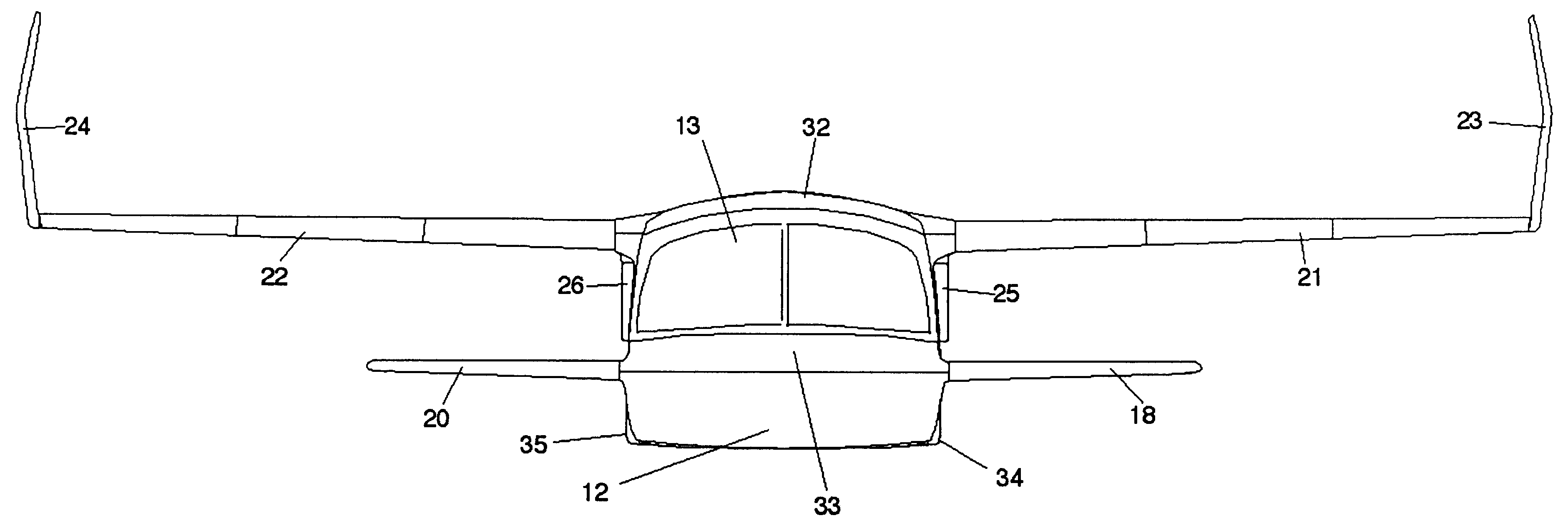
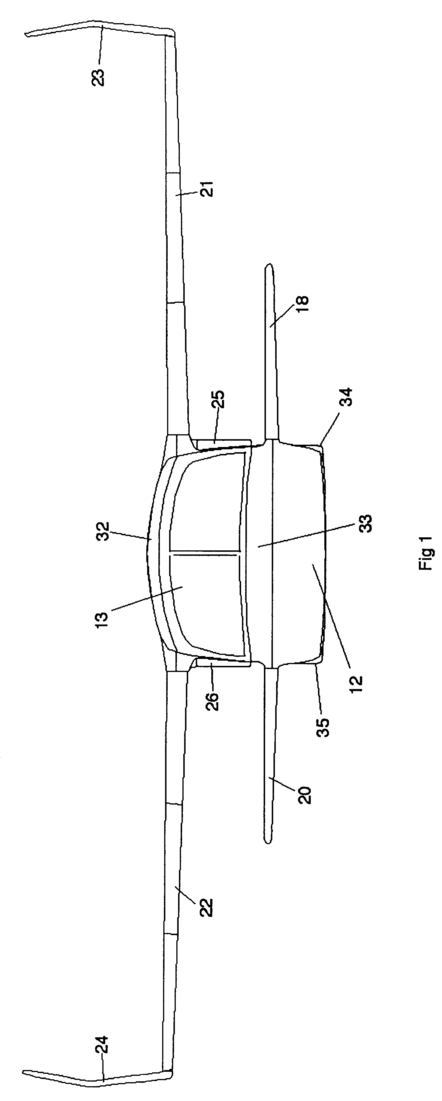
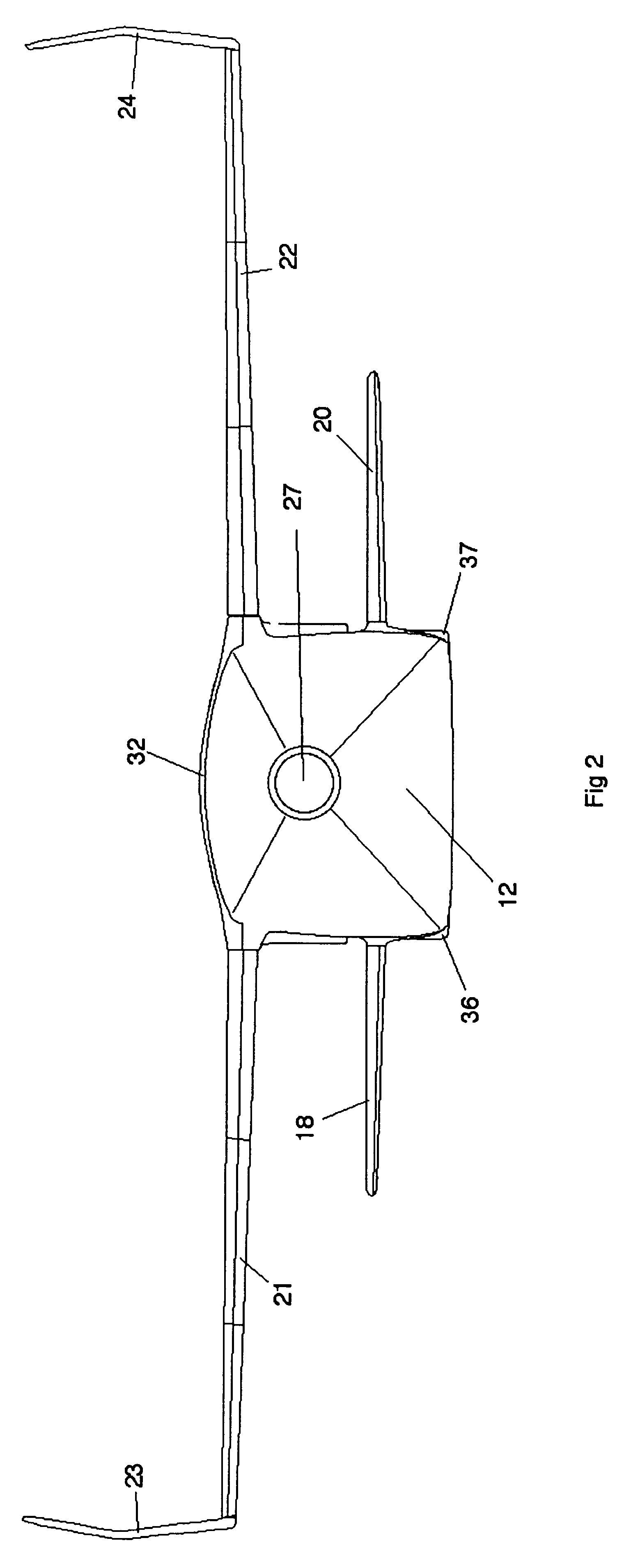
The present invention comprises a vehicle that may be driven on the road as an automobile and also flown as an aircraft. FIGS. 1, 2, 3, 4, 5, and 6 provide front, rear, side, center cross section side, top and bottom views respectively of the present road / air vehicle in air configuration with wheels retracted. The elements shown are a body structure 12, having a cockpit 13, with seating for at least two occupants 79, with access provided by a left occupant access door 28 and corresponding right occupant access door 29. A forward left canard wing 18 and a corresponding right canard wing 20 are shown as well as a left main wing 21 and corresponding right main wing 22 and a left stabilizing fin 23 and corresponding right stabilizing fin 24. A rearward portion contains a jet thrust engine 78 to provide motive power for flight operations with left intake vent 25, a corresponding right intake vent 26 and a single jet thrust outlet 27. A center forward section contains an automobile engine...


PUM


Abstract

A road/air vehicle is able to quickly and easily convert between two configurations, air configuration and road configuration, to facilitate practical operation as both an aircraft and as an automobile. In air configuration the craft includes two laterally symmetrically flight surfaces; a smaller forward canard wing, generally horizontally disposed and a larger rearward main wing generally horizontally disposed with fin surfaces, generally vertically disposed, at each tip. Control surfaces on the main wing, the canard wing and the tip fins severally provide roll control, pitch control and yaw control in flight. The wheels/undercarriage are of a laterally symmetrical rectangular pattern, with the lateral distance between the two forward wheels and the two rearward wheels being similar. The forward wheels are steerable for ground operations. A suitable powerplant drives the rear wheels for ground operations. A second suitable powerplant provides direct atmospheric thrust for flight operations. In road configuration all flight surfaces and avionics sensors are folded and stored inside compartments within the body of the craft. Controls to facilitate both ground and flight operations are available for a single operator to perform the functions of both driver in road configuration and pilot in air configuration.

Description

The present invention relates generally to motorized transportation vehicles, and more specifically to a craft having the ability to interchangeably convert between an aircraft configuration and an automobile configuration. The craft includes numerous novel features relating to the practicality and safety of such a vehicle, such as secure stowage of all flight surfaces and avionics sensors during ground operations, the use of separate, discreet power plants for ground and flight operations and other novel features.The idea of a vehicle, which is capable of both flight operation and highway operation, has been a dream since shortly after the development of the first powered aircraft in the early part of the twentieth century. Numerous inventors have attempted to produce such a combination craft, generally known as a flying car or roadable aircraft. Some of these attempts have met with limited success, in two cases the machines have been type certified by the Civil Aeronautics Agency ...

Claims


Application Information

Patent Timeline
IPC IPC(8): B60F5/00B60F5/02B64C37/00B64C5/00B64C5/12B64C3/00B64C3/56
CPCB60F5/02B64C3/56B64C5/12B64C37/00B60F2301/04
Inventor HAYNES, ROBIN
Owner HAYNES ROBIN
Why Eureka
Try Eureka