
Taking lens device

a technology of taking lens and lens body, which is applied in the field of taking lens body, can solve the problems of unsatisfactory image-sensing performance of zoom lens, ghosting, undue long optical total length of zoom lens,

Inactive Publication Date: 2003-09-16
MINOLTA CO LTD
View PDF7 Cites 18 Cited by
  • Summary
  • Abstract
  • Description
  • Claims
  • Application Information

AI Technical Summary

Problems solved by technology

However, this arrangement includes a diffractive optical element, and therefore the zoom lens, when used as a taking lens system, suffers from ghosts caused by second- and third-order light.
This makes the zoom lens somewhat unsatisfactory in image-sensing performance.
This makes the optical total length of the zoom lens unduly long.
This makes it difficult to reduce the cost and size of the zoom lens.
If the lower limit of conditional formula (1) were to be transgressed, the second lens unit Gr2 would interfere with the third lens unit Gr3 at the wide-angle end W, and this would complicate the mechanical structure of lens barrels.
If the lower limit of conditional formula (2) were to be transgressed, the optical power of the third lens unit Gr3 would be so strong that it would be difficult to correct off-axial curvature of field, in particular, in the portion of the zoom range from the middle position M to the telephoto end T. By contrast, if the upper limit of conditional formula (2) were to be transgressed, the optical power of the third lens unit Gr3 would be so weak that it would be difficult to secure a zoom ratio of about 3.times..
If the lower limit of conditional formula (3) were to be transgressed, the axial thickness of the, negative lens element constituting the first lens unit Gr1 would be so small that the lens element, when made of glass, would be very prone to breakage or, when made of plastic, would cause a slack flow of the material in the molding process.
In either case, it would be impossible to manufacture the lens element on a practical basis.
By contrast, if the upper limit of conditional formula (3) were to be transgressed, the thickness of the first lens unit Gr1 would be so great that, with the resulting large optical total length, it would be impossible to achieve satisfactory compactness.
This would make it impossible to manufacture the lens element on a practical basis.
Moreover, the differences in the heights of axial rays between the front surface and the rear surface of the positive lens element provided in the second lens unit Gr2 would be so small that it would be difficult to correct the axial chromatic aberration that would have occurred at the front surface with the rear surface.
By contrast, if the upper limit of conditional formula (4) were to be transgressed, the thickness of the second lens unit Gr2 would be so great that, with the resulting large optical total length, it would be impossible to achieve satisfactory compactness.
However, if the first lens unit Gr1 is comprised of one negative lens element and the object-side surface of this lens element is given a strong negative optical power, the lens element bends the rays incident thereon so sharply that it is impossible to eliminate the resulting aberration (in particular, off-axial aberration).
In a negative-positive-positive type, the first lens unit Gr1 is the only lens unit that has a negative optical power, and therefore, if the first lens unit Gr1 is kept stationary during zooming, it is impossible to achieve zooming and back focal length adjustment with two positive lens units Gr2, Gr3 alone over the entire zoom range from the wide-angle end W to the telephoto end T. As a result, attempting to secure a zoom ratio of about 3.times. makes it difficult to secure satisfactory performance.

Method used


Image

  • Taking lens device
  • Taking lens device
  • Taking lens device

Examples


Embodiment Construction

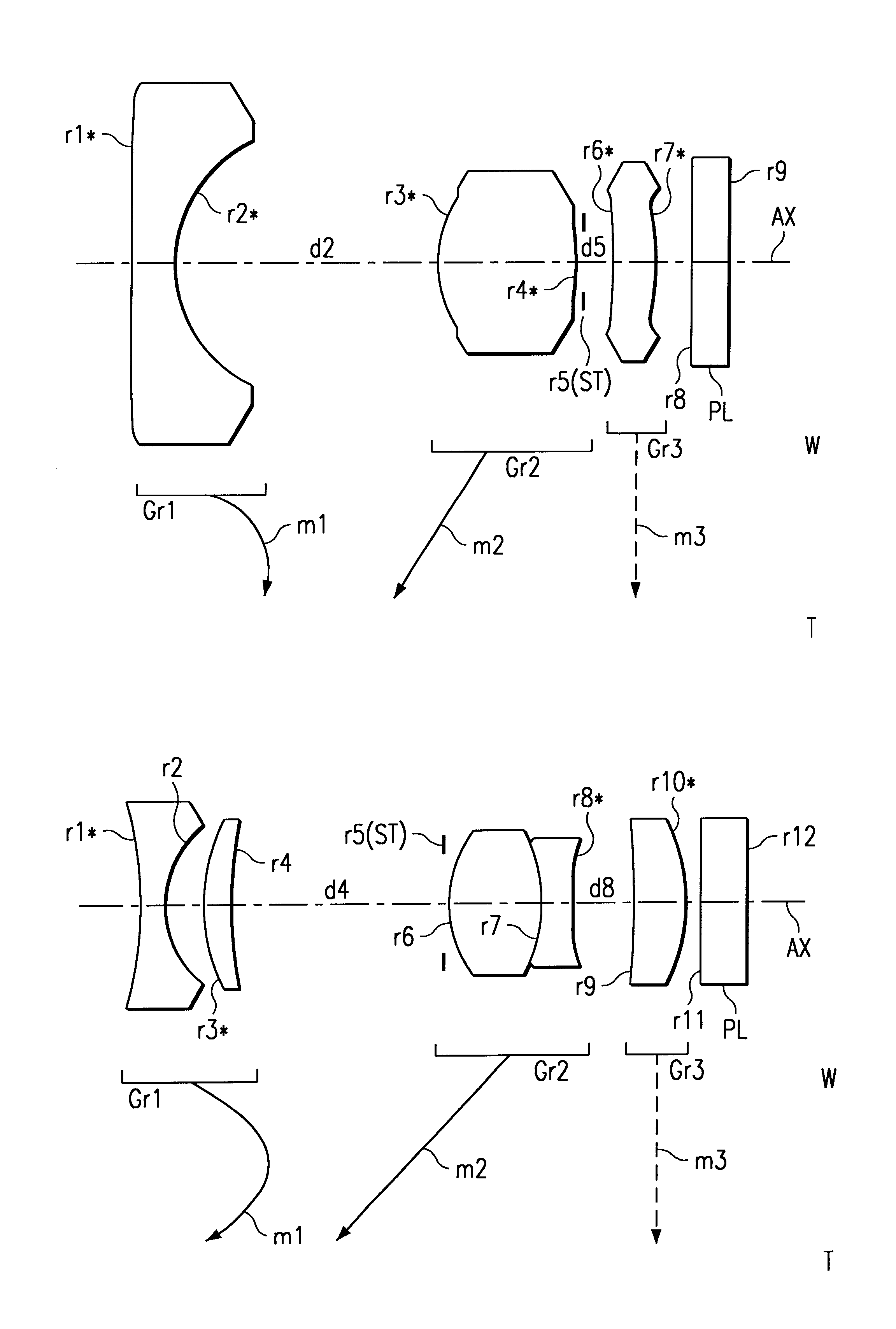
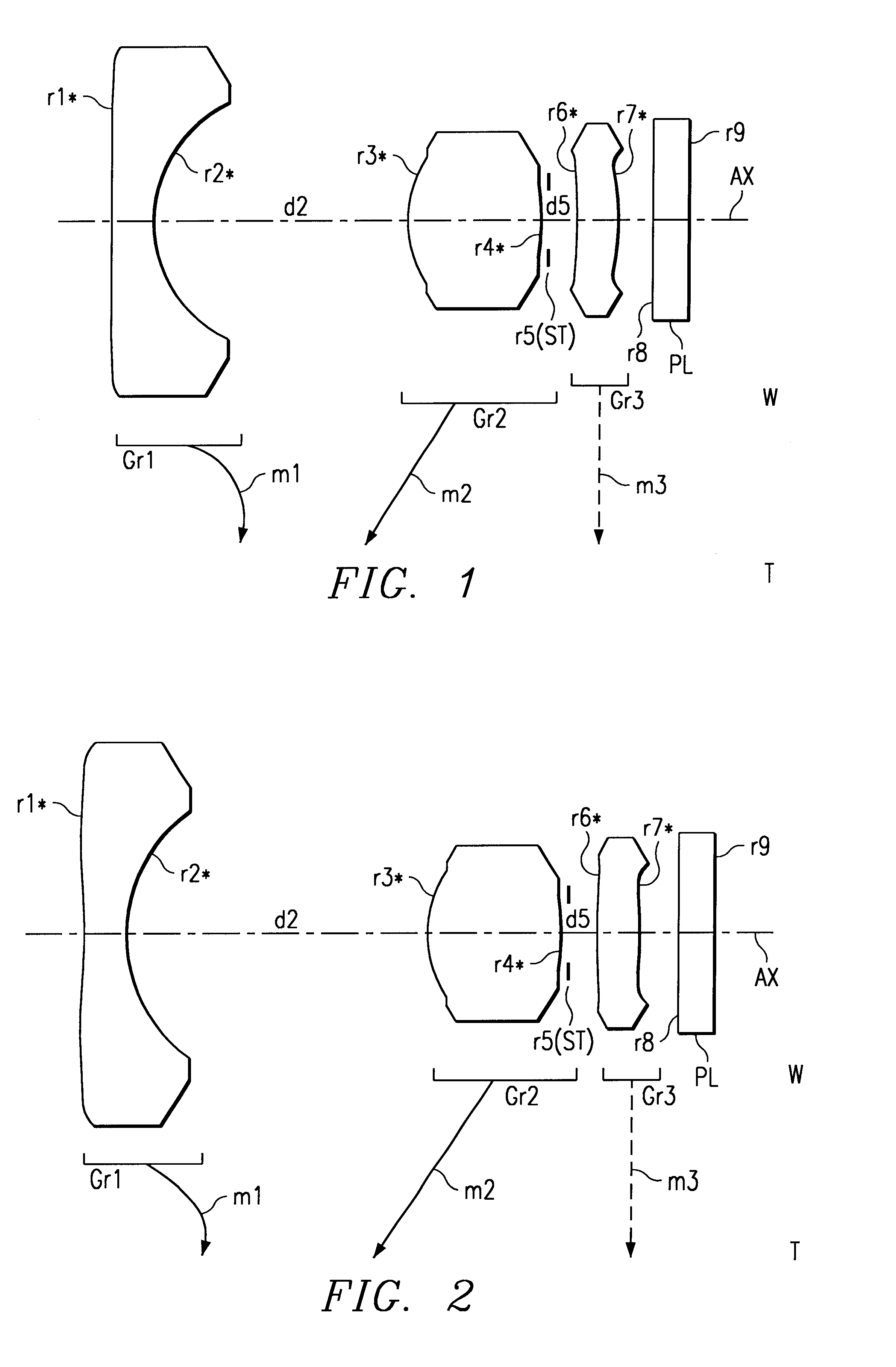
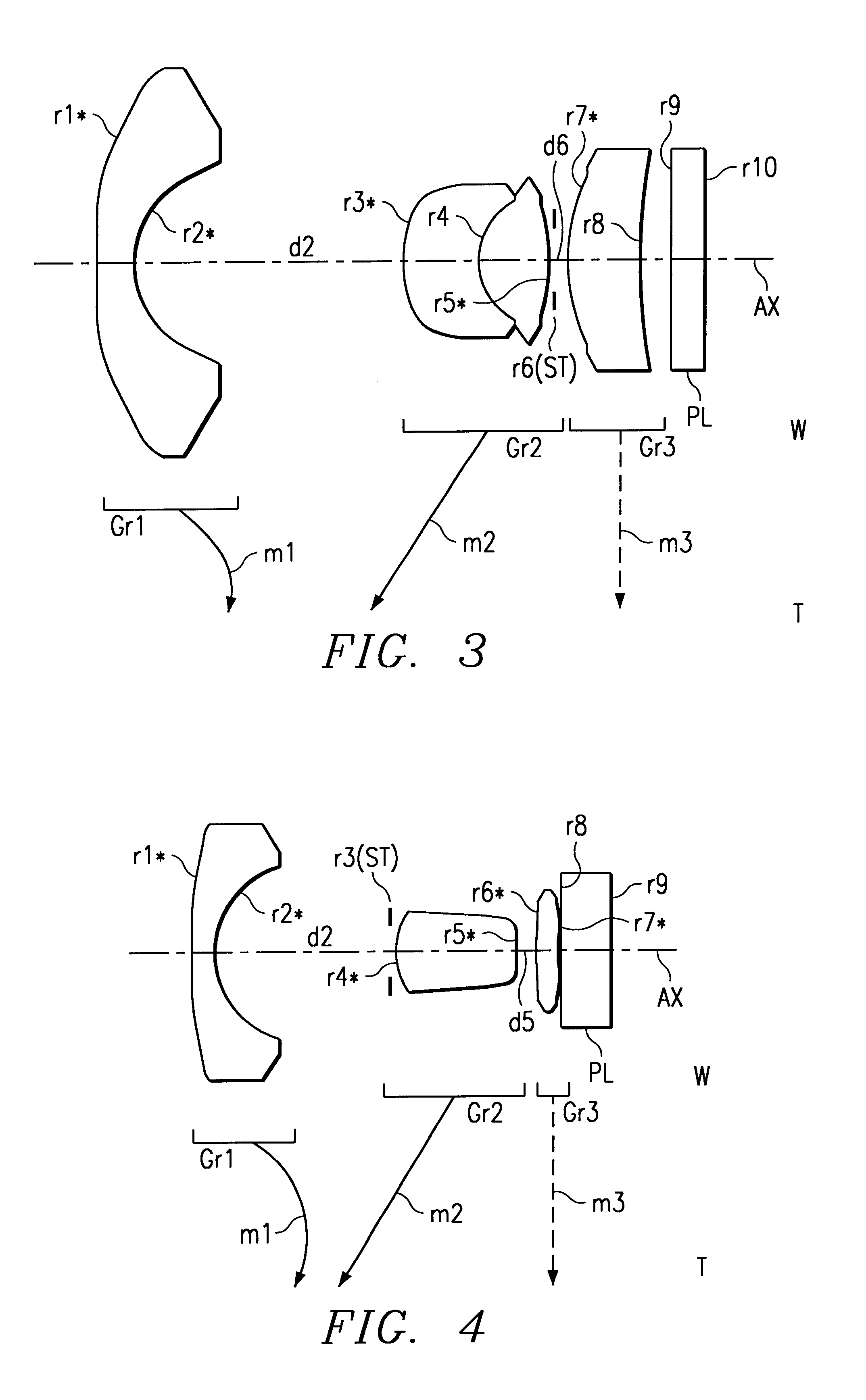
presented below correspond to the first to the sixth embodiments, respectively, described hereinbefore, and the lens arrangement diagrams (FIGS. 1 to 6) showing the lens arrangement of the first to the sixth embodiments apply also to Examples 1 to 6, respectively.

Tables 1 to 6 list the construction data of Examples 1 to 6, respectively. In the construction data of each example, ri (where i=1, 2, 3, . . . ) represents the radius of curvature (mm) of the i-th surface from the object side, di (where i=1, 2, 3, . . . ) represents the i-th axial distance (mm) from the object side, and Ni (where i=1, 2, 3, . . . ) and vi (where i=1, 2, 3, . . . ) respectively represent the refractive index Nd for the d-line and the Abbe number vd of the i-th optical element from the object side. Moreover, in the construction data, for each of those axial distances that vary with zooming (i.e. variable aerial distances), three values are given that are, from left, the axial distance at the wide-angle end (...


PUM


Abstract

Taking lens device has zoom lens system comprised of plurality of lens units and achieves zooming by varying unit-to-unit distances and image sensor that converts optical image formed by zoom lens system into electrical signal. Zoom lens system comprised of, from the object side, first lens unit having negative optical power, second lens unit having positive optical power, and third lens unit having positive optical power. First, second, and third lens units are each comprised of one lens element, and at least the first and second lens units are moved along the optical axis during zooming. Following conditional formula is fulfilled: 0.2<tW2-3 / fW<1.2, where tW2-3 represents optical path length from the most image-side lens surface in second lens unit to the most object-side lens surface in third lens unit at wide-angle end, and fW represents focal length of the entire zoom lens system at wide-angle end.

Description

This application is based on Japanese Patent Applications Nos. 2000-160245 and 2000-368341, filed on May 30, 2000 and Dec. 4, 2000, respectively, the contents of which are hereby incorporated by reference.1. Field of the InventionThe present invention relates to a taking lens device. More specifically, the present invention relates to a taking lens device that optically takes in an image of a subject through an optical system and then outputs the image as an electrical signal by means of an image sensor, for ex ample, a taking lens device that is used as a main component of a digital still camera, a digital video camera, or a camera that is incorporated in or externally fitted to a device such as a digital video unit, a personal computer, a mobile computer, a portable telephone, or a personal digital assistant (PDA). The present invention relates particularly to a taking lens device which is provided with a compact, high-zoom-ratio zoom lens system.2. Description of Prior ArtIn rece...

Claims


Application Information

Patent Timeline
Patent Type & Authority Patents(United States)
IPC IPC(8): G02B15/177G02B13/00G02B9/12G02B15/163G02B13/18
CPCG02B9/12G02B13/0035G02B13/006G02B13/009G02B15/177G02B27/4216G02B27/0037G02B15/143503
Inventor HAGIMORI, HITOSHI
Owner MINOLTA CO LTD
Learn More