Venturi type air distribution system

a technology of air distribution system and venturi type, which is applied in ventilation system, heating type, lighting and heating apparatus, etc., can solve the problems of noisy operation, known system does not use air induction unit for mixing return air and primary air,

Inactive Publication Date: 2003-09-23
AIRTEX MFG PARTNERSHIP
View PDF6 Cites 29 Cited by
  • Summary
  • Abstract
  • Description
  • Claims
  • Application Information

AI Technical Summary

Problems solved by technology

However, this known system does not use air induction units for mixing return air and primary air.
This known air conditioning system does not employ any induction unit that relies on the venturi effect and, because it employs a blower, it will be quite noisy when it is operating.

Method used


Image

  • Venturi type air distribution system
  • Venturi type air distribution system
  • Venturi type air distribution system

Examples


second embodiment

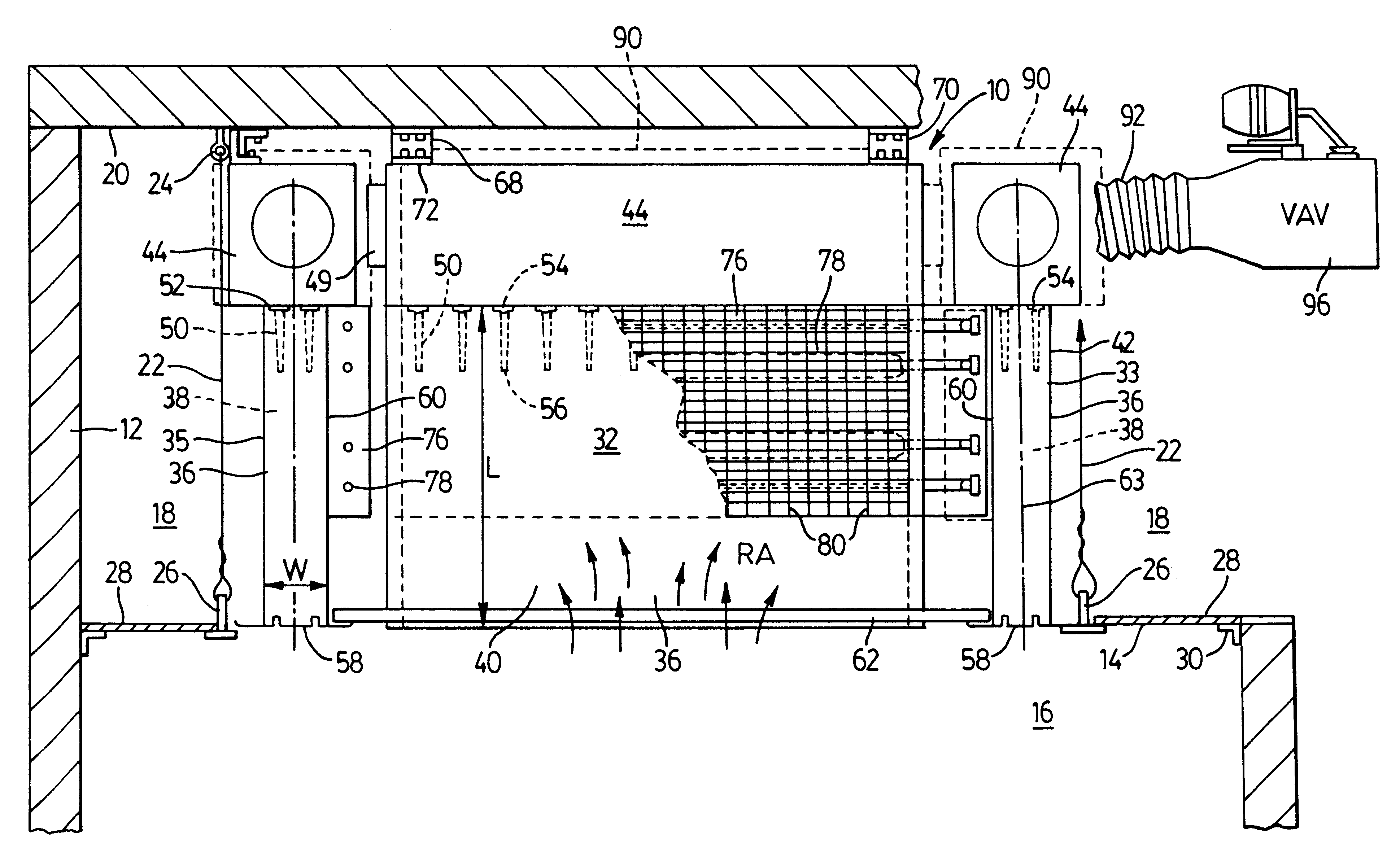
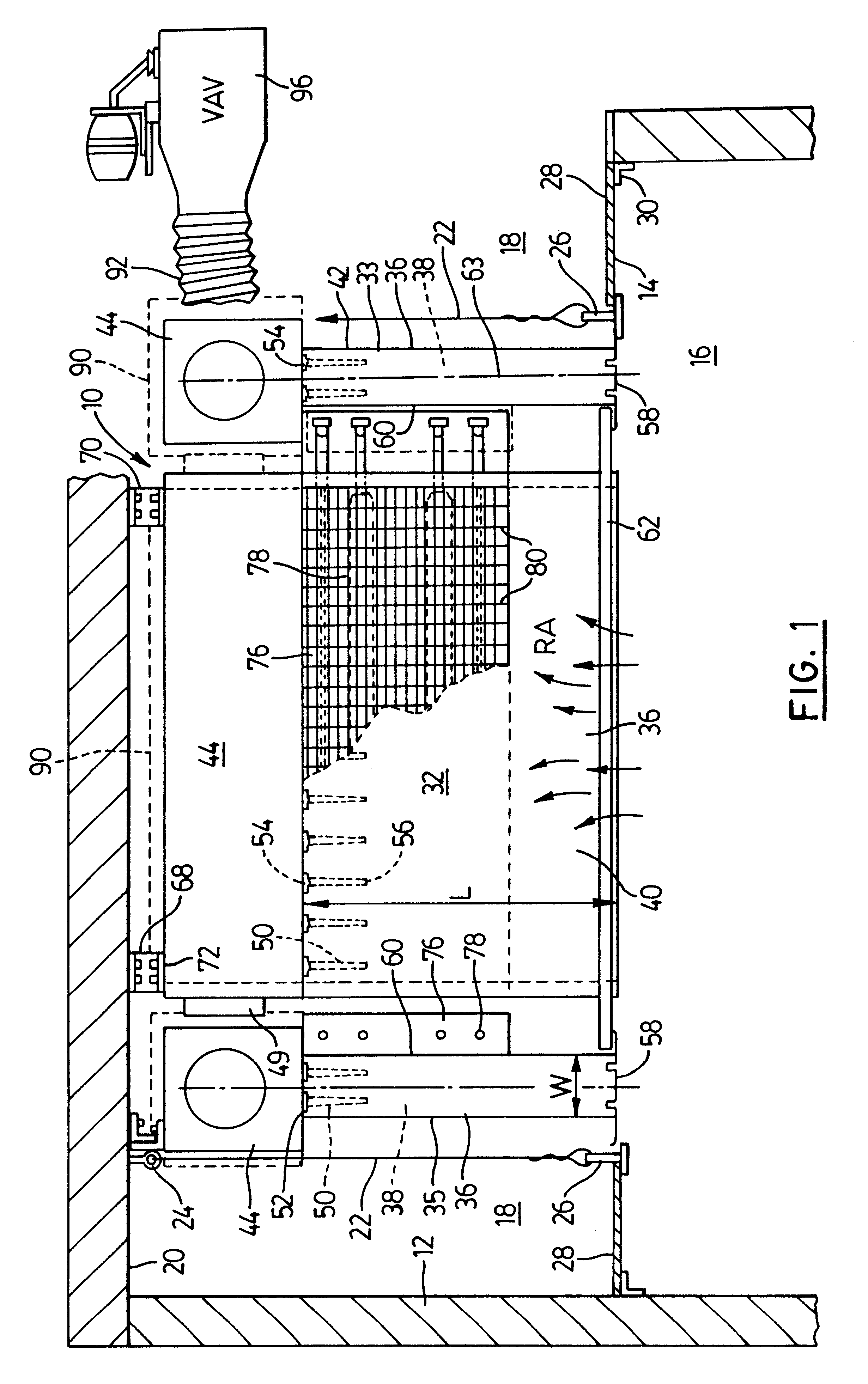
With the induction unit assembly illustrated in FIGS. 1 to 4, a reasonable amount of height is required between the ceiling level at 14 and the structural ceiling at 20 in order to accommodate the height of the induction units. In one typical embodiment of this type of air handling system, the total height of each induction unit assembly is about 23 inches and a small amount of additional room may be required to attach the assembly to the structural ceiling 20. If this much room is not available for the induction unit assembly, then a user of this system can employ the embodiment illustrated in FIGS. 5 to 7 of the drawings. In FIGS. 5 to 7, the same reference numerals will be used to indicate those features which are the same as in the embodiment of the induction unit assembly illustrated in FIGS. 1 to 4. This second embodiment of induction unit assembly is indicated generally at 110. The assembly includes four induction units 112 to 115, each of which has the same height, this heig...

first embodiment

Each of the induction units has an elongate, horizontally extending air plenum section 118. The position of this air plenum section differs from the position of the air plenum section 44 in the first embodiment in that the major section of the plenum section 118 is located on the outer side of the air mixing section 36 rather than above the air mixing section. Each plenum section 118 has a bottom 120 connected to an outer wall 122. The inner wall of the air plenum section is provided by the vertical wall 42 of the air mixing section. At the top of the air plenum section 118 is a connecting duct section 124 that includes a top wall 126, this wall extending over the air mixing section 36. There is a relatively short vertical wall 128 which extends downwardly from the top wall to the top edge of the air mixing section. It will be understood that air is free to flow in the direction indicated by the arrow Z in FIG. 5 from the main portion of the air plenum section 118 into the region di...


PUM


Abstract

An air handling system for a building having a ceiling and enclosed space, the system including four interconnected induction units for mounting adjacent the ceiling. These units form four sides of a rectangular assembly. Each induction unit includes an air plenum section and an air mixing section connected to a side of the air plenum section and forming an elongate air mixing chamber that extends downwardly to an air outlet. Supporting members mount the induction unit assembly at the ceiling so that each air mixing section when viewed in transverse, vertical cross-section extends at a substantial angle, which in a preferred embodiment is about 90 degrees, to the ceiling during use of the apparatus. Return air is drawn by venturi effect created by a fast flow of primary air into each air mixing chamber and heated or cooled at the heat exchanging coils. The units can provide a mixed air flow that flows downwardly from the outlets.

Description

BACKGROUND OF THE ARTThis unit relates to an air handling system for a building and, in particular, such a system employing one or more induction units adapted to mix two air flows.A variety of air handling systems for both large and small buildings are already known in the air handling industry. Air handling systems both for residential and commercial buildings can include the use of a central heating system that includes a fan unit capable of blowing heated air through air ducts that deliver the air to the various rooms of the building. When this system is used in conjunction with a central air conditioner, it is also capable of providing cool air to the various rooms through the air ducts. A relatively large fan is generally required for a large commercial or industrial building. Air silencers can be installed on both the inlet side and outlet side of these large fans to reduce the noise levels created by the operation of such fans.It is also known to provide so called induction ...

Claims


Application Information

Patent Timeline
Patent Type & Authority Patents(United States)
IPC IPC(8): F24F1/01
CPCF24F1/01F24F2221/14
Inventor AKHTAR, SALMANGRANEK, GERHARD
Owner AIRTEX MFG PARTNERSHIP
Why Eureka
Try Eureka