

Method and device for non-destructive analysis of perforation in a material
a perforation and non-destructive technology, applied in the field of methods and devices for non-destructive analysis of perforations in materials, can solve the problems of excessive pore density and insufficient size, and achieve the effects of rapid inspection, accurate and efficient inspection, and reduced image siz
- Summary
- Abstract
- Description
- Claims
- Application Information
AI Technical Summary
Benefits of technology
Problems solved by technology
Method used
Image

Examples
example 1
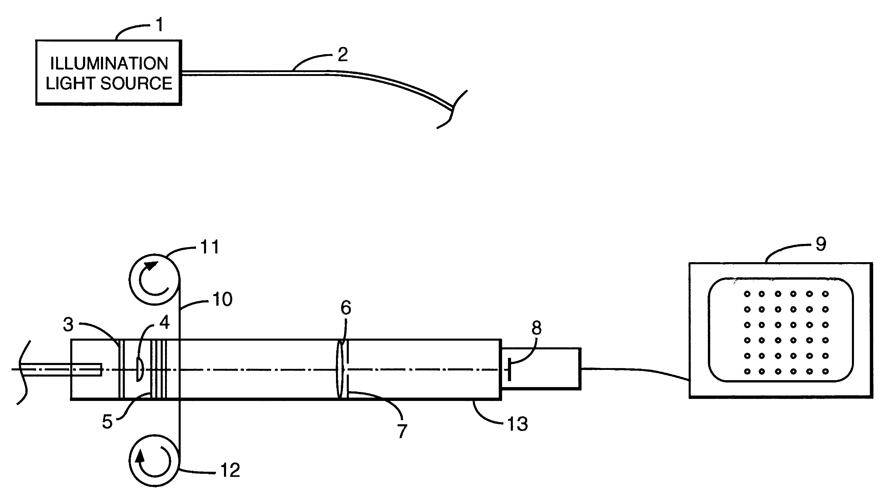
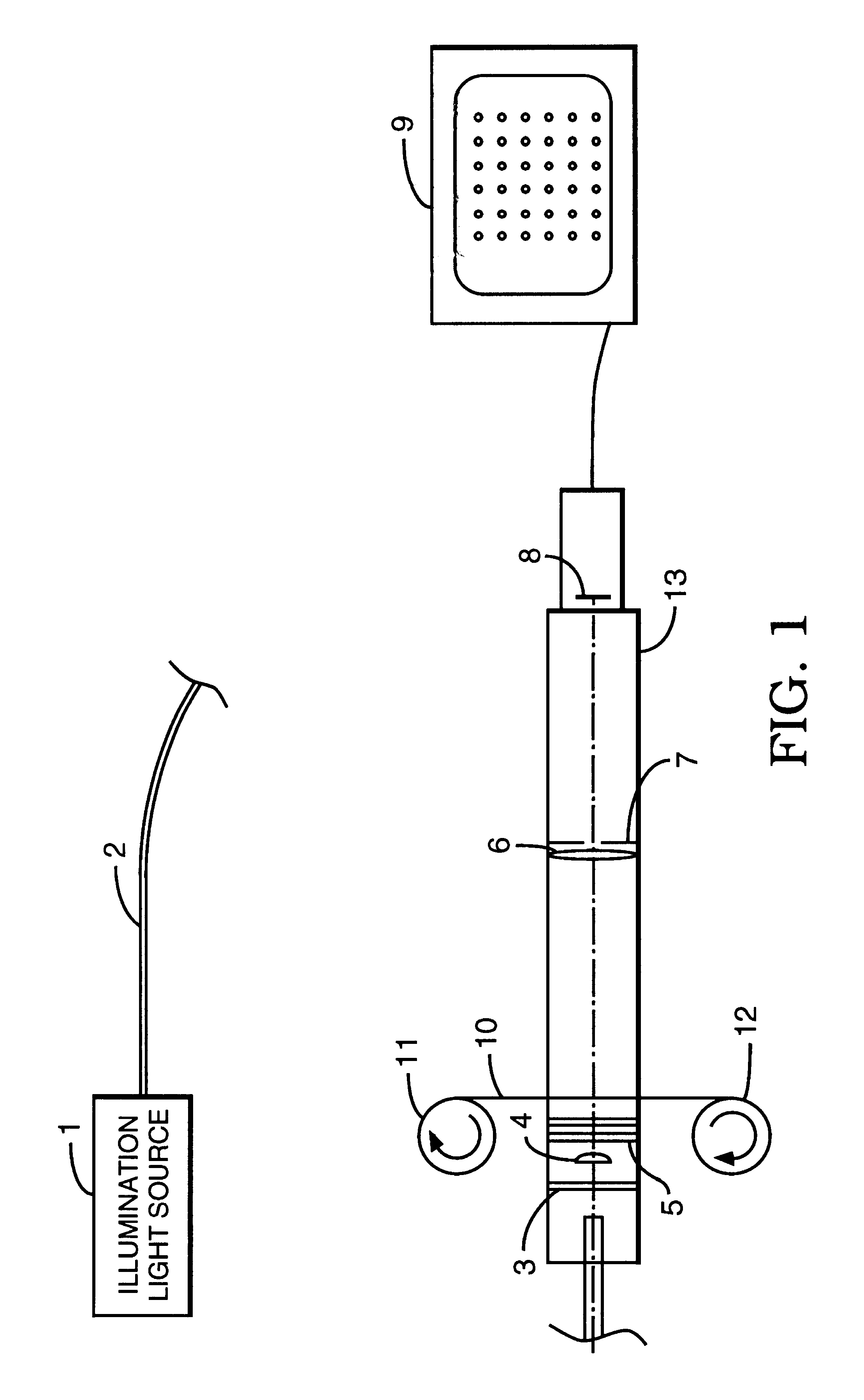
This experiment demonstrates the use of the method of the invention to inspect holes in a sample. A mercury arc lamp of the type commonly used for ultraviolet adhesive curing was used for the light source. The ultraviolet portion of the spectrum was specifically isolated between 300 and 400 nanometers utilizing appropriate reflective and transmissive optical filter elements well known to those skilled in the art. This ultraviolet portion consisted mainly of the strong emission line from mercury at 365 nanometers. The filtered light was guided via a commonly used liquid light guide which transmits near ultraviolet in the spectral range selected. At the output of the fiber, a diffuse reflectance glass was used to provide additional homogenization of the beam exiting the guide. A condensing lens was then used to collimate the light and illuminate the sample to be inspected. The sample was a polyimide film. Spectral filters were located in the collimated light to ensure the rejection of...
example 2
This experiment demonstrates the use of the method of the invention to inspect holes in a sample. A mercury arc lamp of the type commonly used for ultraviolet adhesive curing was used for the light source. The ultraviolet portion of the spectrum was specifically isolated between 300 and 400 nanometers utilizing appropriate reflective and transmissive optical filter elements well known to those skilled in the art. This ultraviolet portion consisted mainly of the strong emission line from mercury at 365 nanometers. The filtered light was guided via a commonly used liquid light guide which transmits near ultraviolet in the spectral range selected. At the output of the fiber, a diffuse reflectance glass was used to provide additional homogenization of the beam exiting the guide. A condensing lens was then used to collimate the light and illuminate the sample to be inspected. The sample was a polyimide film. Spectral filters were located in the collimated light to ensure the rejection of...
PUM
| Property | Measurement | Unit |
|---|---|---|
| pore diameter | aaaaa | aaaaa |
| diameter | aaaaa | aaaaa |
| aperture diameter | aaaaa | aaaaa |
Abstract
Description
Claims
Application Information