Method and device for non-destructive analysis of perforations in a material

a perforation and non-destructive technology, applied in the field of non-destructive analysis, can solve the problems of insufficient size or shape, large holes, and large number of holes formed, and achieve the effects of small features and fast, accurate and efficient inspection

Inactive Publication Date: 2007-11-27
ARADIGM
View PDF21 Cites 3 Cited by
  • Summary
  • Abstract
  • Description
  • Claims
  • Application Information

AI Technical Summary

Benefits of technology

[0023]An advantage of the invention is that pore arrays can be quickly, accurately and efficiently inspected. Another advantage of the invention is that the fabricated pore sizes and shapes can be very tightly controlled, and smaller features can be achieved, leading to a better performing final product.
[0024]A feature of the invention is that different types of light sources can be used and different types of filters can be used and positioned differently relative to the sheet being inspected.
[0025]Another feature of the invention is that the sheet may be moved relative to the light source and detector or the light source and / or detector may be moved relative to the sheet.

Problems solved by technology

If the detector does not detect a desired quantity of light, either an insufficient number of holes has been formed or the holes are of insufficient size or shape or some combination thereof.
Further, if too much light is detected, either the holes are too large, have an undesired shape, or there are too many holes present in the sheet.

Method used


Image

  • Method and device for non-destructive analysis of perforations in a material
  • Method and device for non-destructive analysis of perforations in a material
  • Method and device for non-destructive analysis of perforations in a material

Examples


example 1

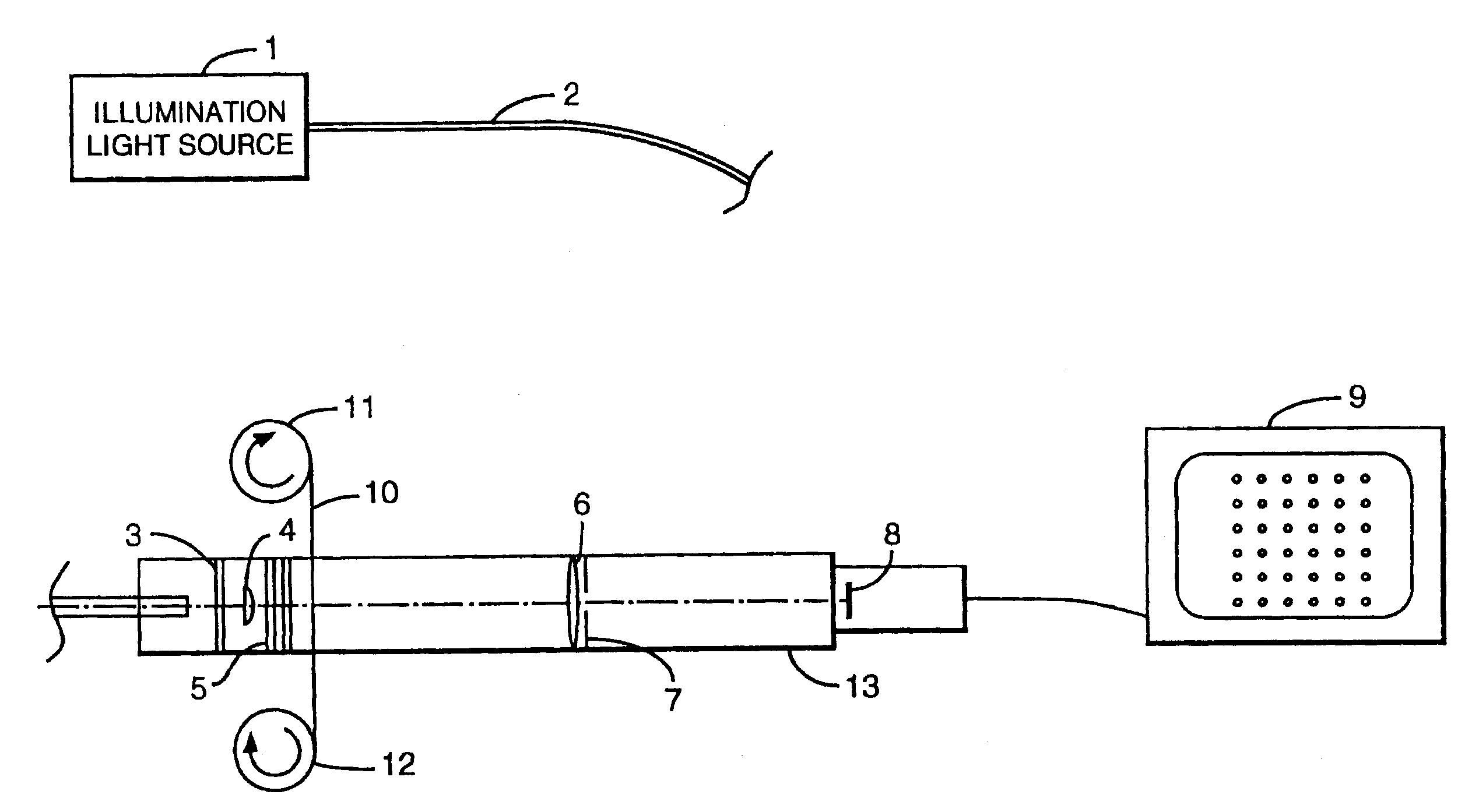
[0076]This experiment demonstrates the use of a method of the invention to inspect holes in a sample. A mercury arc lamp of the type commonly used for ultraviolet adhesive curing was used for the light source. The ultraviolet portion of the spectrum was specifically isolated between about 300 and 400 nanometers utilizing appropriate reflective and transmissive optical filter elements well known to those skilled in the art. This ultraviolet portion consisted mainly of the strong emission line from mercury at 365 nanometers. The filtered light was guided via a commonly used liquid light guide which transmits near ultraviolet in the spectral range selected. At the output of the fiber, a diffuse reflectance glass was used to provide additional homogenization of the beam exiting the guide. A condensing lens was then used to collimate the light and illuminate the sample to be inspected. The sample was a polyimide film. Spectral filters were located in the collimated light to ensure the re...

example 2

[0077]This experiment demonstrates the use of a method of the invention to inspect holes in a sample. A mercury arc lamp of the type commonly used for ultraviolet adhesive curing was used for the light source. The ultraviolet portion of the spectrum was specifically isolated between about 300 and 400 nanometers utilizing appropriate reflective and transmissive optical filter elements well known to those skilled in the art. This ultraviolet portion consisted mainly of the strong emission line from mercury at 365 nanometers. The filtered light was guided via a commonly used liquid light guide which transmits near ultraviolet in the spectral range selected. At the output of the fiber, a diffuse reflectance glass was used to provide additional homogenization of the beam exiting the guide. A condensing lens was then used to collimate the light and illuminate the sample to be inspected. The sample was a polyimide film. Spectral filters were located in the collimated light to ensure the re...

example 3

[0078]This experiment demonstrates the use of a method of the invention to form and inspect spots in a 25 micrometer thick polyimide sheet. The energy source used was a frequency tripled niobium yttrium based LASER emitting 355 nm wavelength pulses, each having approximately 0.4 to about 0.6 microjoule of energy. The LASER was focused on spot having a diameter of about 12 to about 15 micrometer and produced a hole with an exit diameter between about 0.4 and about 0.6 micrometer. The formed hole passed approximately 0.5 to about 10 picojoules which was detected by a silicone diode detector. Based on the signal from the detector, a discrete electronic feedback circuit comprising a comparator, a reference voltage and logic gates sent an electronic signal to the LASER to stop generating light pulses.

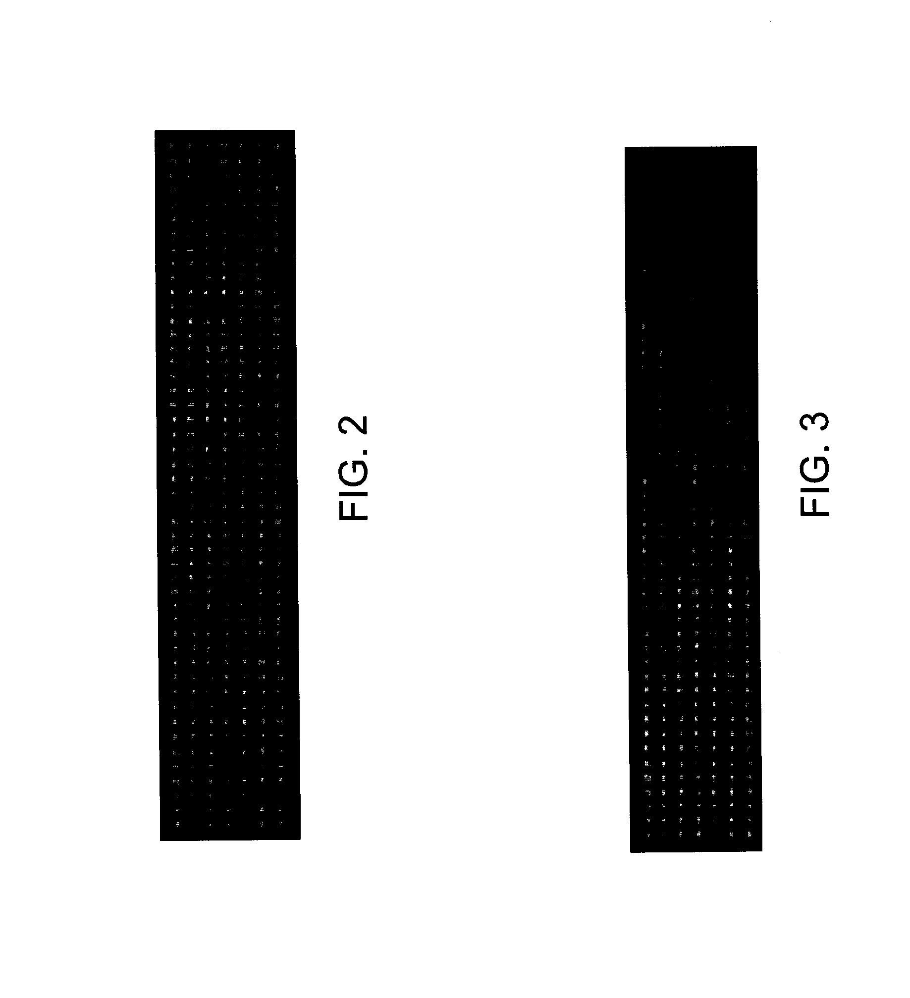
[0079]Several sets of pore arrays were fabricated using the same light source and optical system drilling one pore at a time. Some arrays were produced using a predetermined number of pulses...


PUM

PropertyMeasurementUnit
diameteraaaaaaaaaa
diameteraaaaaaaaaa
diameteraaaaaaaaaa

Abstract

Method for fabricating and inspecting small holes in a material are disclosed. The method includes directing light onto the material and through the holes formed in the material, and then collecting the light passing through the holes in the material onto a detector. The methods further include analyzing the light for properties of the holes, and modifying the process based these detected properties.

Description

FIELD OF THE INVENTION[0001]The invention relates generally to methods of non-destructive analysis. More particularly, the invention relates to a method and device for quickly and non-destructively analyzing an array of small holes precisely placed in a material such as a thin film.BACKGROUND OF THE INVENTION[0002]In different areas of technology it is desirable to make use of a thin sheet of material which has an array of regularly spaced, very small holes therein. For example, such might be used in the manufacture of various electronic components. Thin sheets which have one or more holes in them could also be used in the formation of components used in ink jet printers or fuel injectors. A more direct application of such a pore array is as a filter. The pore size and pore density could be adjusted to wide range of filter applications. Alternatively, liquid formulations containing a drug could be moved through such a porous member to create an aerosol for inhalation.[0003]One of th...

Claims


Application Information

Patent Timeline
Patent Type & Authority Patents(United States)
IPC IPC(8): G01N21/00
CPCB01D67/0034G01N21/894B01D2323/50B01D2323/34G01N2021/8812
Inventor SCHUSTER, JEFFREY A.SRINIVASAN, SUDARSANWILBANKS, THOR MILLER
Owner ARADIGM
Why Eureka
Try Eureka