Optical sheets

a technology of optical sheets and sheets, applied in the field of optical sheets, can solve the problems of difficult manufacturing of crts having larger sizes, light interference, and limited space required for mounting, and achieve the effects of reducing light loss, increasing brightness, and reducing contact with the panel

Active Publication Date: 2010-04-08
KOLON IND INC
View PDF14 Cites 33 Cited by
  • Summary
  • Abstract
  • Description
  • Claims
  • Application Information

AI Technical Summary

Benefits of technology

[0028]According to the present invention, an optical sheet functions to uniformly diffuse light emitted from a light guide plate or a diffusion sheet and to increase brightness at the same time, includes a prism layer which can be easily formed on a light diffusion layer, and can reduce the loss of light.
[0029]In consideration of light diffusivity and light-collecting functions, part of a conventional optical fi...

Problems solved by technology

Conventionally, a CRT (Cathode Ray Tube), which is bulky, was widely used therefor, but faces considerable limitations in terms of the space required to mount it, thus making it difficult to manufacture CRTs having larger sizes.
In this way, in order to effectively transfer such emitted light to the liquid crystal panel, a plurality of films having various functions is mounted, thereby causing light interference, including a Newton's Ring phenomenon, occurring as a result of use of the plurality of films, or a wet-out phenomenon, by which air is removed from the contact surfa...

Method used


Image

  • Optical sheets
  • Optical sheets
  • Optical sheets

Examples


example 1

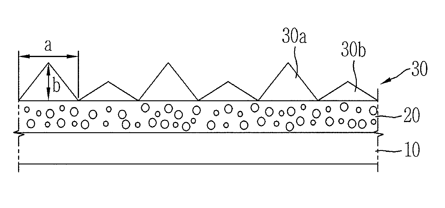
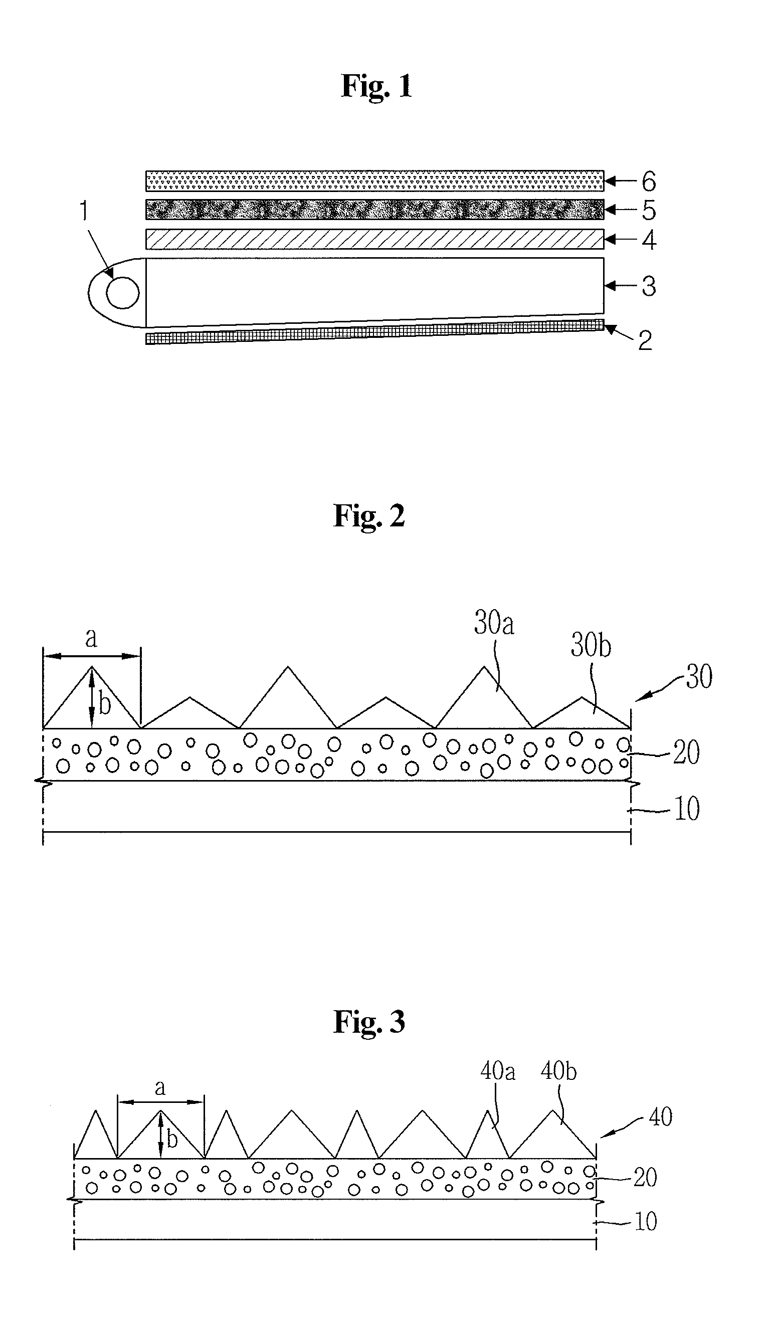
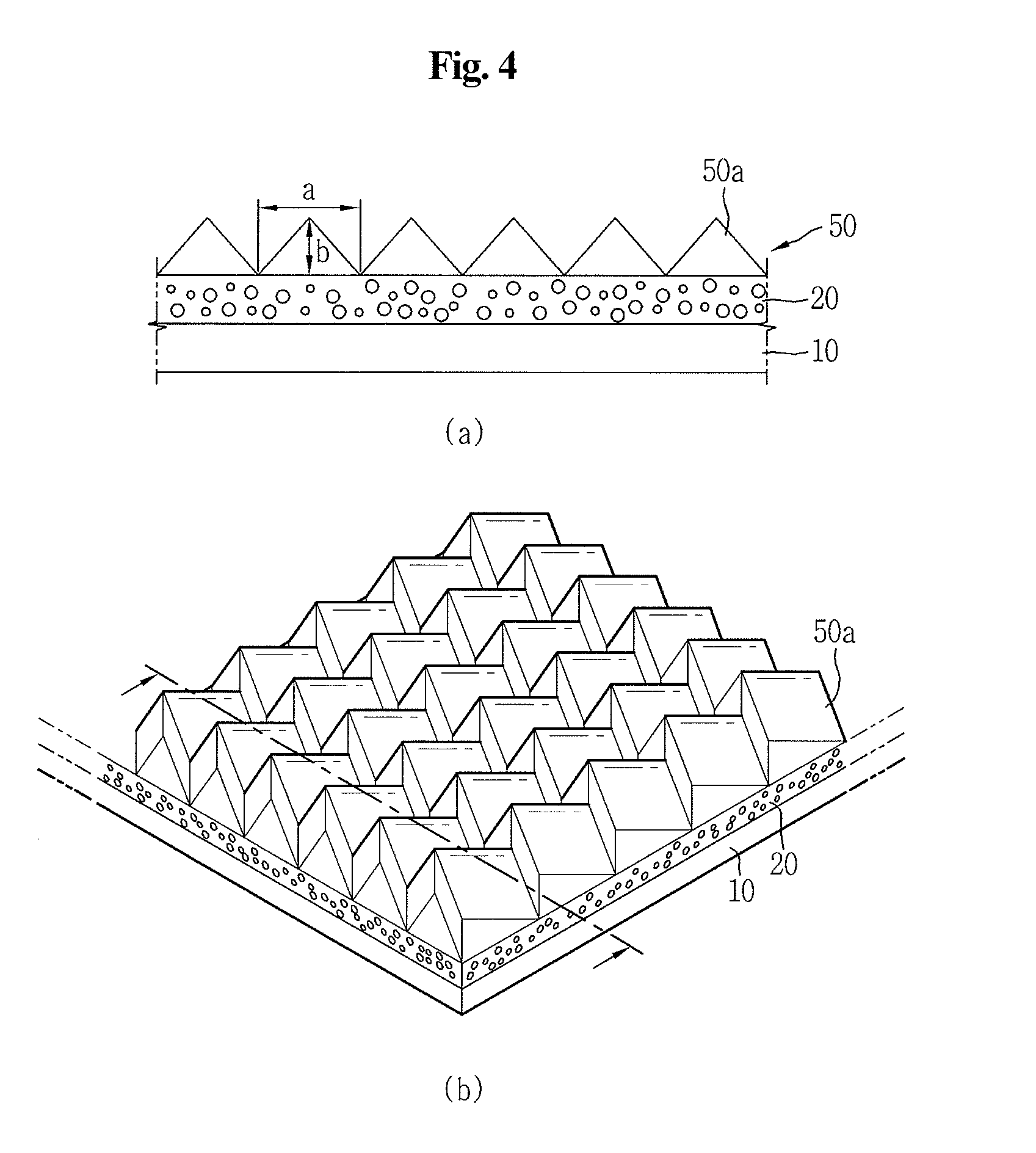
[0072]100 parts by weight of acrylic resin (52-666, Aekyung Chemical) was diluted with 70 parts by weight of methylethylketone and 50 parts by weight of toluene, thus preparing a binder resin having a refractive index of 1.50, after which spherical polymethylmethacrylate particles (MH20F, Kolon) having an average particle size of 20 μm and a refractive index of 1.50 were mixed in an amount of 110 parts by weight based on the binder resin, monodispersed in the form of a mono layer using a milling machine, applied on one surface of a super-transparent polyethyleneterephthalate film (FHSS, Kolon) 188 μm thick as a transparent substrate layer using a gravure coater, and then cured at 120° C. for 60 sec, thus forming a light diffusion layer (refractive index: 1.50) having a dry thickness of 25 μm.

[0073]Further, on one surface of the cured light diffusion layer, a photosensitive composition comprising 75 parts by weight of urethane acrylate, 20 parts by weight of 2-phenylethyl methacrylat...

example 2

[0074]An optical composite film was manufactured in the same manner as in Example 1, with the exception that a prism layer having nonlinear triangular prisms and a refractive index of 1.53 was formed on one surface of the light diffusion layer.

example 3

[0075]An optical composite film was manufactured in the same manner as in Example 1, with the exception that the light-diffusing particles were dispersed in a multilayer form in the course of formation of the light diffusion layer. As such, the light diffusion layer was 30˜35 μm thick and had a refractive index of 1.50.


PUM


Abstract

Disclosed is an optical sheet for use in liquid crystal displays, which simultaneously functions to uniformly diffuse light emitted from a light guide plate and a diffusion plate and to increase brightness, decreases the loss of light, and enables the fabrication of thinner liquid crystal displays.

Description

TECHNICAL FIELD [0001]The present invention relates to an optical sheet for use in liquid crystal displays.BACKGROUND ART [0002]As industrial society has developed toward an advanced information age, the importance of electronic displays as a medium for displaying and transferring various pieces of information is increasing day by day. Conventionally, a CRT (Cathode Ray Tube), which is bulky, was widely used therefor, but faces considerable limitations in terms of the space required to mount it, thus making it difficult to manufacture CRTs having larger sizes. Accordingly, CRTs are being replaced with various types of flat panel displays, including liquid crystal displays (LCDs), plasma display panels (PDPs), field emission displays (FEDs), and organic electroluminescent displays. Among such flat panel displays, in particular,[0003]LCDs, a technologically intensive product resulting from a combination of liquid crystal-semiconductor techniques, are advantageous because they are thin...

Claims


Application Information

Patent Timeline
IPC IPC(8): G02B5/02G09F13/04
CPCG02B5/045G02B5/02
Inventor KIM, KYUNG NAMKIM, HYUN JUNGKIM, SANG KYUNKIM, HYUN JINPARK, JONG MINKANG, CHUNG SEOCK
Owner KOLON IND INC
Why Eureka
Try Eureka