Thin-film magnetic head with heater in overcoat multilayer, head gimbal assembly with thin-film magnetic head, and magnetic disk drive apparatus with head gimbal assembly

a thin-film magnetic head and heater technology, applied in the direction of maintaining head carrier alignment, instruments, metal sheet cores, etc., can solve the problems of abnormal signal (thermal asperity, heater is likely to bring about crashes, etc., to reduce dms, avoid crashes reliably and stably, and small value

Active Publication Date: 2005-12-08
TDK CORPARATION
View PDF16 Cites 33 Cited by
  • Summary
  • Abstract
  • Description
  • Claims
  • Application Information

AI Technical Summary

Benefits of technology

[0014] Therefore, it is an object of the present invention to provide a thin-film magnetic head with a heater capable of reducing dMS to a small value and reliably and stably avoiding crashes between portions close to the trailing edge and the magnetic disk surface by controlling the swelling shape of the PTR surface with high thermal efficiency while suppressing manufacturing variations, an HGA provided with this thin-film magnetic head and a magnetic disk drive apparatus provided with this HGA.

Problems solved by technology

However, during writing signals, Joule heat from the coil layer within an inductive write head element and heat caused by eddy-current loss from the upper and lower pole layers are generated.
As a result, when the designed value of dMS is very small, the protruding MR effect element may contact the magnetic disk surface and frictional heat produced by the contact may cause the electrical resistance value of the MR effect element to change, producing an abnormal signal (thermal asperity).
Here, the thin-film magnetic head provided with such a heater is likely to bring about crashes due to the swelling of the overcoat layer.
As a result, despite the fact that dMS which is the distance between the end of the magnetic head element and the magnetic disk surface is secured within a predetermined value, the swelling portion of the PTR surface close to the trailing edge may contact the magnetic disk surface, producing crashes and causing damage to the magnetic disk surface and thin-film magnetic head.
However, even if the method of further recessing the portion close to the trailing edge of the PTR surface is used, it is difficult to sufficiently suppress the positively generated swelling of the portion close to the trailing edge, depending on the state in which the heater is heated.
Therefore, according to this manufacturing method, the processed parts are quite minute and the amount of grinding or etching is also a very small quantity, and therefore it is unavoidable to produce a large processing variation.
As a result, the swelling shape of the processed PTR surface varies from one head to another, resulting in a problem that it is difficult to stably avoid the crashes.
Furthermore, the process such as polishing with quite high accuracy is applied after the entire thin-film magnetic head is formed, which increases manufacturing man-hours considerably.
There is also another problem that minute shavings, etc., produced during the process may be stuck to the PTR surface, causing an adverse effect on the head operation.
Moreover, processing the PTR surface alone cannot live up to an expectation for an improvement on a degree of the swelling in the PTR surface per the amount of heat from the heater, that is, thermal efficiency in generating a TPTP phenomenon.
As a result, the amount of heat propagating from the heater to the MR effect element increases, causing a decrease in the reading performance in the MR effect element having high temperature dependency of output.

Method used


Image

  • Thin-film magnetic head with heater in overcoat multilayer, head gimbal assembly with thin-film magnetic head, and magnetic disk drive apparatus with head gimbal assembly
  • Thin-film magnetic head with heater in overcoat multilayer, head gimbal assembly with thin-film magnetic head, and magnetic disk drive apparatus with head gimbal assembly
  • Thin-film magnetic head with heater in overcoat multilayer, head gimbal assembly with thin-film magnetic head, and magnetic disk drive apparatus with head gimbal assembly

Examples


Embodiment Construction

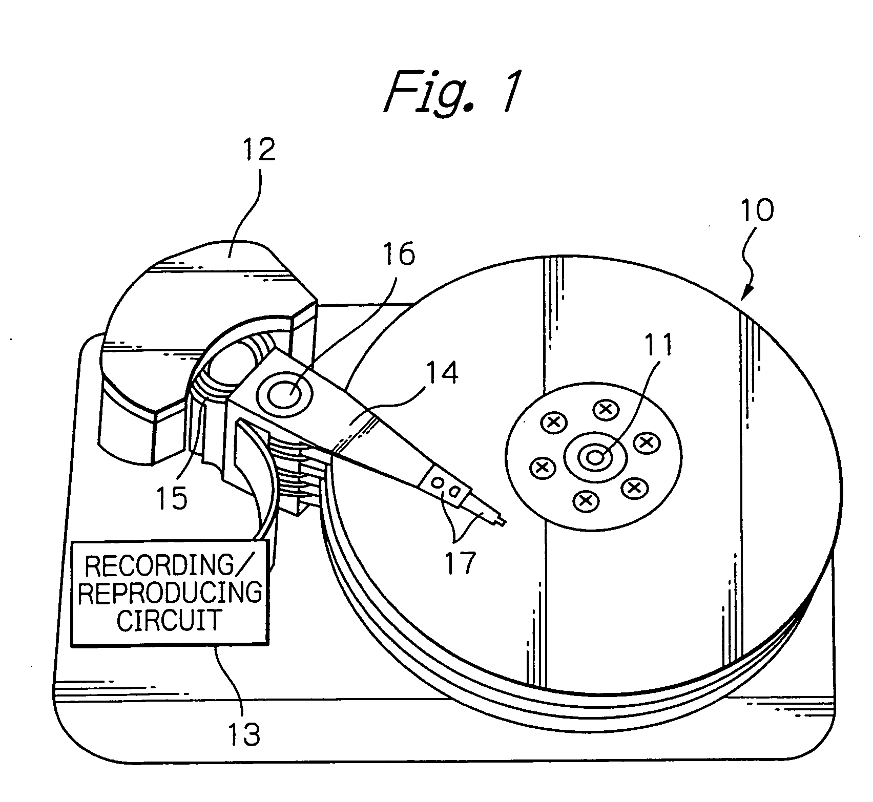
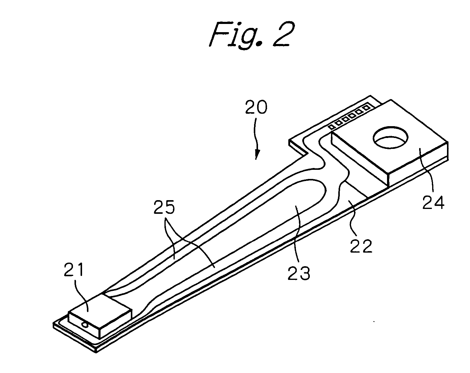
[0048]FIG. 1 is a perspective view schematically showing the constitution of main components of a magnetic disk drive apparatus according to an embodiment of the present invention, FIG. 2 is a perspective view showing the whole of an HGA and FIG. 3 is a perspective view of a thin-film magnetic head (slider) mounted at an end portion of the HGA.

[0049] In FIG. 1, reference numeral 10 denotes a plurality of magnetic disks rotating around a rotational axis 11 of a spindle motor, 12 denotes an assembly carriage device for positioning a thin-film magnetic head (slider) on a track, 13 denotes a recording and reproducing circuit for controlling read / write operations and heat operations of the thin-film magnetic head.

[0050] The assembly carriage device 12 is provided with a plurality of drive arms 14. These drive arms 14 are rotatable around a pivot bearing axis 16 through a voice coil motor (VCM) 15 and stacked in the direction along this axis 16. An HGA 17 is provided at an end portion o...


PUM

PropertyMeasurementUnit
thicknessaaaaaaaaaa
thicknessaaaaaaaaaa
thicknessaaaaaaaaaa

Abstract

A thin-film magnetic head according to the present invention comprises: a substrate; at least one magnetic head element formed on the substrate; an overcoat multilayer composed of a plurality of overcoat layers, formed on the substrate so as to cover the at least one magnetic head element; and at least one heating element to be heated at least during operation of the at least one magnetic head element, the at least one heating element provided in the overcoat multilayer, and a coefficient of thermal expansion of an overcoat layer located farthest from the substrate in the overcoat multilayer being smaller than a coefficient of thermal expansion of an overcoat layer located closest to the substrate in the overcoat multilayer.

Description

PRIORITY CLAIM [0001] This application claims priorities from Japanese patent application No. 2004-167266, filed on Jun. 4, 2004 and Japanese patent application No. 2005-102637, filed on Mar. 31, 2005, which are incorporated herein by reference. BACKGROUND OF THE INVENTION [0002] 1. Field of the Invention [0003] The present invention relates to a thin-film magnetic head with a heater in an overcoat multilayer, a head gimbal assembly (HGA) with the thin-film magnetic head and a magnetic disk drive apparatus with the HGA. [0004] 2. Description of the Related Art [0005] In a magnetic disk drive apparatus, a thin-film magnetic head writes and reads signals to / from a magnetic disk that is rotated by a spindle motor. The thin-film magnetic head has an inductive write head element and a magnetoresistive (MR) effect read head element formed on a slider substrate fixed at an end portion of an suspension of a HGA. During writing or reading signals, the thin-film magnetic head is driven to a d...

Claims


Application Information

Patent Timeline
Patent Type & Authority Applications(United States)
IPC IPC(8): G11B5/127G11B5/147G11B5/31G11B5/33G11B5/58
CPCG11B5/3106G11B5/3136G11B5/314G11B5/581G11B5/6064
Inventor UMEHARA, TSUYOSHIOTA, NORIKAZUTAGAMI, KATSUMICHIMATSUKUMA, HIROKIOYAMA, NOBUYAKOIDE, SOJIMIZOGUCHI, YOSHIYUKIYAMADA, KAZUHIDE
Owner TDK CORPARATION
Why Eureka
Try Eureka