Slightly conducting insulators for cathode-ray tube (CRT) applications

a technology of insulator and cathode-ray tube, which is applied in the manufacture of electric discharge tubes/lamps, magnetic deflection devices, electric discharge tubes, etc., and can solve problems such as undesirable charging, failure of focus masks, and failure of insulator materials on focus masks to charg

Inactive Publication Date: 2003-09-30
THOMSON LICENSING SA
View PDF1 Cites 4 Cited by
  • Summary
  • Abstract
  • Description
  • Claims
  • Application Information

AI Technical Summary

Benefits of technology

The present invention relates to a color cathode-ray tube (CRT) having an evacuated envelope with an electron gun therein for generating an electron beam. The envelope further includes a faceplate panel having a luminescent screen with phosphor elements on an interior surface thereof. A focus mask, having a plurality of spaced-apart first conductive strands, is located adjacent to an effective picture area of the screen. The spacing between the first conductive strands defines a plurality of apertures substantially parallel to the phosphor elements on the screen. Each of the first conductive strands has a substantially continuous slightly conductive insulating material layer formed on a screen facing side thereof. A plurality of second conductive wires are oriented substantially perpendicular to the plurality of first conductive strands and are bonded thereto by the slightly conductive insulating material layer. The slightly conductive insulating material layer is a composite material comprising one or more transition metal oxides and a lead-zinc-borosilicate glass.

Problems solved by technology

HV flashover is undesirable because it may cause an electrical short circuit between the two sets of conductive lines, leading to the subsequent failure of the focus mask.
Also, when the electron beams from the electron gun are directed toward the color emitting phosphors on the screen, backscattered electrons from the screen may cause the insulator material on the focus mask to charge.
Such charging is undesirable because it may interfere with the ability of the focus mask to direct the electron beams toward the color emitting phosphors formed on the screen, as well as cause HV flashover between the conductive lines of the focus mask.

Method used


Image

  • Slightly conducting insulators for cathode-ray tube (CRT) applications
  • Slightly conducting insulators for cathode-ray tube (CRT) applications
  • Slightly conducting insulators for cathode-ray tube (CRT) applications

Examples


Embodiment Construction

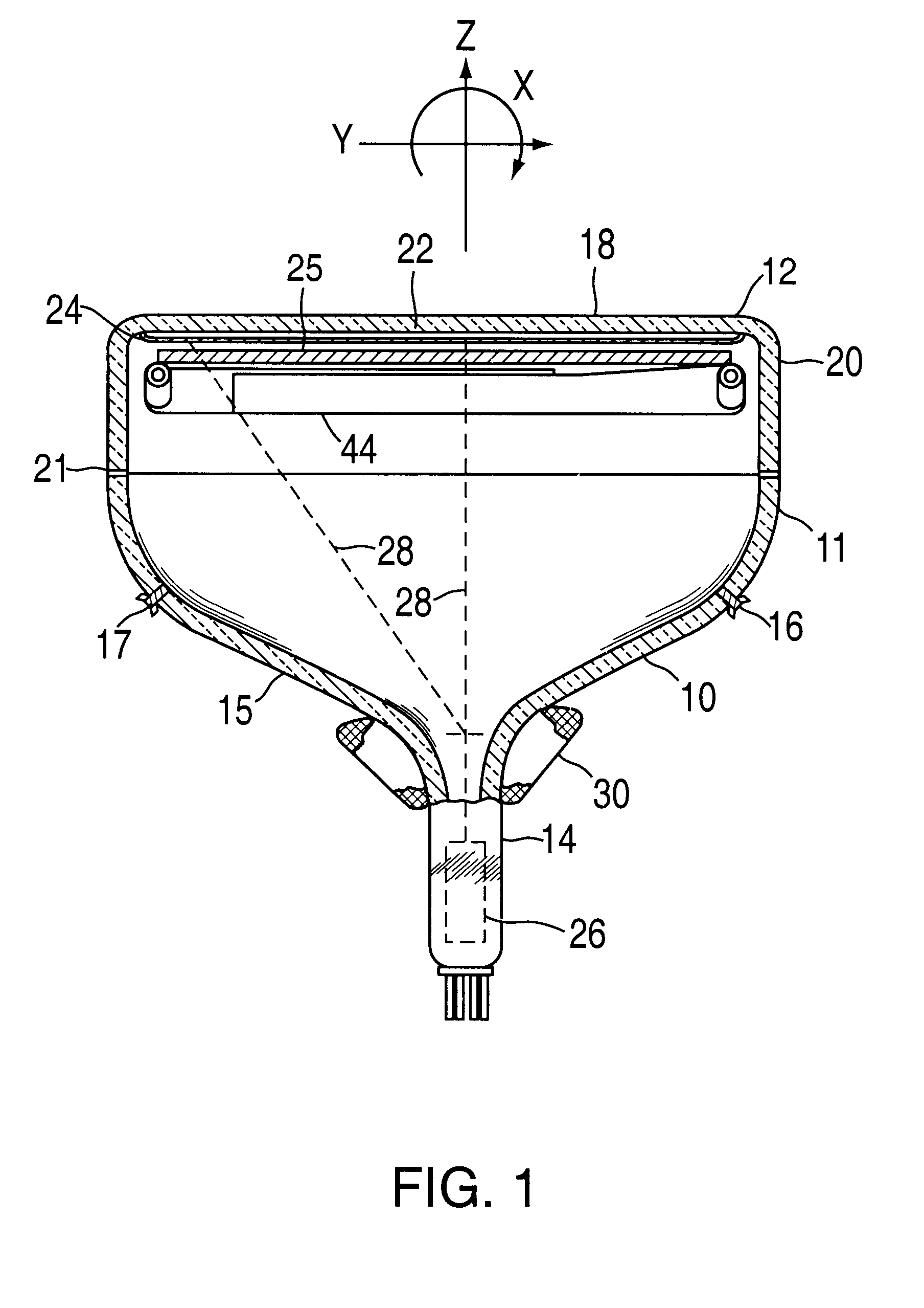
FIG. 1 shows a color cathode-ray tube (CRT) 10 having a glass envelope 11 comprising a faceplate panel 12 and a tubular neck 14 connected by a funnel 15. The funnel 15 has an internal conductive coating (not shown) that is in contact with, and extends from, a first anode button 16 to the neck 14. A second anode button 17, located opposite the first anode button 16, is not contacted by the conductive coating.

The faceplate panel 12 comprises a viewing faceplate 18 and a peripheral sidewall 20, or skirt, that is sealed to the funnel 15 by a glass frit 21. A three-color luminescent phosphor screen 22 is coated on the inner surface of the faceplate 18. The screen 22 is a line screen, shown in detail in FIG. 5, that includes a multiplicity of screen elements comprising red-emitting, green-emitting, and blue-emitting phosphor elements, R, G, and B, respectively, arranged in triads, each triad including a phosphor line of each of the three colors. Preferably, a light absorbing matrix 23 sep...


PUM


Abstract

A color cathode-ray tube (CRT) has an evacuated envelope with an electron gun therein for generating an electron beam. The envelope further includes a faceplate panel having a luminescent screen with phosphor elements on an interior surface thereof. A focus mask, having a plurality of spaced-apart first conductive strands, is located adjacent to an effective picture area of the screen. The spacing between the first conductive strands defines a plurality of apertures substantially parallel to the phosphor elements on the screen. Each of the first conductive strands has a substantially continuous slightly conductive insulating material layer formed on a screen facing side thereof. A plurality of second conductive wires are oriented substantially perpendicular to the plurality of first conductive strands and are bonded thereto by the slightly conductive insulating material layer. The slightly conductive insulating material layer is a composite material comprising one or more transition metal oxides and a lead-zinc-borosilicate glass.

Description

BACKGROUND OF THE INVENTION1. Field of the InventionThis invention relates to a color cathode-ray tube (CRT) and, more particularly to a color CRT including a focus mask.2. Description of the Background ArtA color cathode-ray tube (CRT) typically includes an electron gun, an aperture mask, and a screen. The aperture mask is interposed between the electron gun and the screen. The screen is located on an inner surface of a faceplate of the CRT tube. The screen has an array of three different color-emitting phosphors (e.g., green, blue, red) formed thereon. The apertured mask functions to direct electron beams generated in the electron gun toward appropriate color emitting phosphors on the screen of the CRT tube.The aperture mask may be a focus mask. Focus masks typically comprise two sets of conductive lines (or wires) that are arranged approximately orthogonal to each other, to form an array of openings. Different voltages are applied to the two sets of conductive lines so as to crea...

Claims


Application Information

Patent Timeline
Patent Type & Authority Patents(United States)
IPC IPC(8): H01J29/46H01J29/81
CPCH01J29/81H01J2229/585
Inventor THALER, BARRY JAYHEYMAN, PHILIP MICHAELQUINN, ROBERT LEONQUINN, RICHARD JOSEPHYANG, LIYOU
Owner THOMSON LICENSING SA
Why Eureka
Try Eureka