System for multiplexing acoustic emission (AE) instrumentation

a technology of acoustic emission and a system, applied in the field of acoustic monitoring devices, can solve the problems of ineffective ae monitoring in monitoring acoustic, significant disadvantages of having one data acquisition channel per sensor system, and added weight, space, power, etc. to an ae system

Inactive Publication Date: 2003-09-30
DIGITAL WAVE CORP +1
View PDF5 Cites 101 Cited by
  • Summary
  • Abstract
  • Description
  • Claims
  • Application Information

AI Technical Summary

Problems solved by technology

As such, AE monitoring is extremely inefficient in monitoring acoustic emissions that occur at sporadic and random intervals and rates.
The disadvantages of having one channel of data acquisition per sensor system are significant.
These disadvantages include added weight, space, power, cost, etc. to an AE system.
For aerospace applications, these additional weight and power requirements are unacceptable.
Although conventional multiplexing reduces the number of data acquisition channels, a number of sensors are not actively monitored when they are disconnected from the data acquisition hardware.
However, the use of large numbers of channels that are required

Method used


Image

  • System for multiplexing acoustic emission (AE) instrumentation
  • System for multiplexing acoustic emission (AE) instrumentation

Examples


example 2

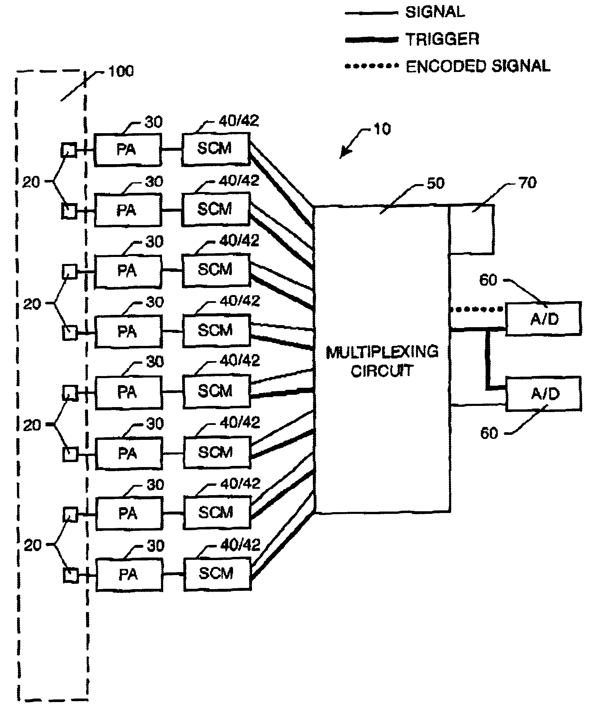
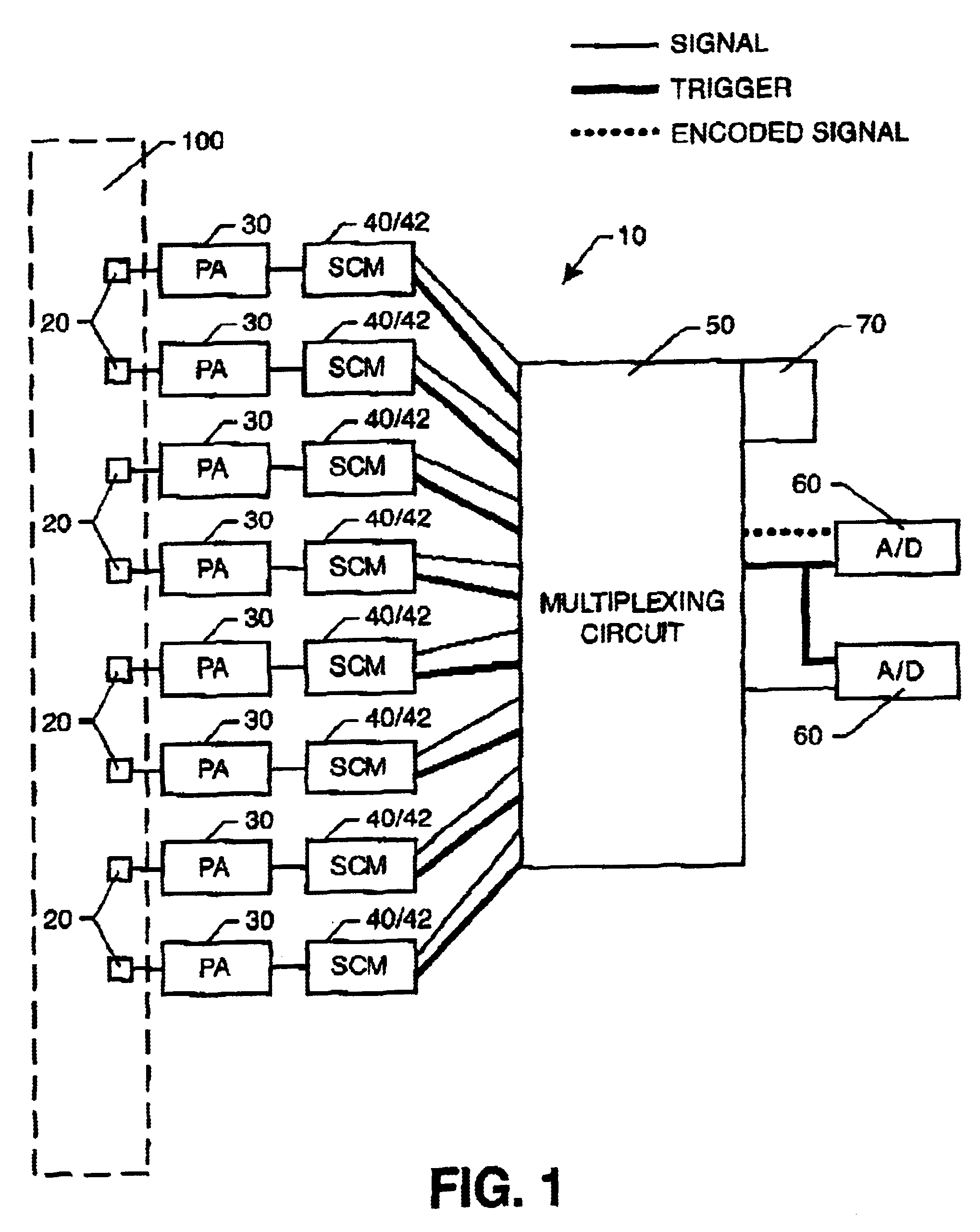
AE sensors are temporary attached in a linear array along an oil pipe. The AE sensors are attached to pre-amplifiers that connect to signal conditioning modules tied to a multiplexing circuit. As areas of the pipe begin to fail, vibrations in the form of acoustic emissions are collected by the AE sensors and amplified by the pre-amplifiers. When the acoustic emissions reach a level to cause a triggering event, the SCM relays the trigger signal to the multiplexing circuit. The multiplexing circuit rapidly switches to allow the conditioned signals from the neighboring AE sensors to be passed to the data acquisition channels. The acoustic emissions are collected from the adjacent AE sensors and recorded to determine the location and magnitude of the failing areas of the pipe.

example 3

AE sensors are permanently molded into a ship hull in a planar array. The AE sensors are attached to pre-amplifiers that connect to signal conditioning modules tied to a multiplexing circuit. As the ship hull experiences forces, the acoustic emissions are collected by the AE sensors and amplified by the pre-amplifiers. When the acoustic emissions reach a level to cause a triggering event at one of the AE sensors, the SCM relays the trigger signal to the multiplexing circuit. The multiplexing circuit rapidly switches to allow the conditioned signals from the neighboring AE sensors to be passed to the data acquisition channels. The acoustic emissions collected from adjacent AE sensors next to the triggered AE sensor are recorded to determine the location of the triggering event, and assess the likelihood of ship hull failure.

example 4

AE sensors are permanently molded into a spatial array within a solid propellent in a space shuttle. The AE sensors are attached to pre-amplifiers that connect to signal conditioning modules tied to a multiplexing circuit. Vibrations are monitored by the AE sensors and amplified by the pre-amplifiers. When the acoustic emissions reach a level to cause a triggering event at one of the AE sensors, the SCM relays the trigger signal to the multiplexing circuit. The multiplexing circuit rapidly switches to allow the conditioned signals from the neighboring AE sensors to be passed to the data acquisition channels. The acoustic emissions collected from adjacent AE sensors next to the triggered AE sensor are recorded to determine the location of the triggering event, and assess the likelihood of damage to the propellent. With the occurrence of particular triggering events, the propellent is automatically jettisoned from the space shuttle.


PUM


Abstract

An acoustic monitoring device has at least two acoustic sensors with a triggering mechanism and a multiplexing circuit. After the occurrence of a triggering event at a sensor, the multiplexing circuit allows a recording component to record acoustic emissions at adjacent sensors. The acoustic monitoring device is attached to a solid medium to detect the occurrence of damage.

Description

1. Field of the InventionThe present invention relates to an acoustic monitoring device. More particularly, the acoustic monitoring device has a multiplexing circuit that records acoustic activity with the occurrence of a triggering event. Most particularly, the acoustic monitoring device may be used to detect, identify and assess damage within a solid medium.2. Brief Description of the Related ArtGenerally in acoustic emission (AE) monitoring, sensors remain active with each sensor having its own acquisition channel. As such, AE monitoring is extremely inefficient in monitoring acoustic emissions that occur at sporadic and random intervals and rates.In a typical AE instrument, signals from each sensor are monitored by their own channel or data acquisition hardware, requiring the same number of channels of acquisition as acoustic sensors. In AE instruments which have fewer channels of data acquisition hardware than sensors, two approaches of switching sensors to data acquisition cha...

Claims


Application Information

Patent Timeline
IPC IPC(8): G01M7/00G01M7/02G01N29/36G01N29/14G01H1/00
CPCG01H1/00G01M7/025G01N29/14G01N29/36G01N2291/106
Inventor PROSSER, WILLIAM H.PEREY, DANIEL F.GORMAN, MICHAEL R.SCALES, EDGAR F.
Owner DIGITAL WAVE CORP
Why Eureka
Try Eureka