Device for measuring a fill level of a liquid in a container

a technology for measuring devices and liquids, which is applied in the direction of instruments, machines/engines, and using reradiation. it can solve the problems of swelling and deformation of containers such as motor vehicle plastic fuel tanks, and the complicated sealing of containers in a complicated fashion

Inactive Publication Date: 2003-10-07
MANNESMANN VDO AG
View PDF12 Cites 30 Cited by
  • Summary
  • Abstract
  • Description
  • Claims
  • Application Information

AI Technical Summary

Benefits of technology

This configuration reliably protects the ultrasonic sensor against contact with the liquid located in the container. Accordingly, the ultrasonic sensor cannot be attacked by the liquid located in the container. Furthermore, sealing in the wall of the container is not required because the wall of the container is not penetrated by the measuring tube. The device according to the present invention allows a particularly reliable measurement of the filling level in the container. Furthermore, the device according to the present invention comprises a simple design that can be produced very cost-effectively. Of course, a float may optionally be arranged in the measuring tube as is known.
In accordance with another embodiment of the present invention, compensating openings having a damping element for damping the pressure compensation are arranged at at least one end of the tube for preventing foaming in the measuring tube. Furthermore, fluctuations in the liquid column in the measuring tube are reliably damped thereby.

Problems solved by technology

A disadvantage of the known device that the ultrasonic sensor contacts the liquid in the container and the container must be sealed in a complicated fashion.
Accordingly, the ultrasonic sensor for measuring a fill level in a fuel tank requires a very complicated and expensive encapsulation.
However, containers such as fuel tanks produced from plastic for motor vehicles, in particular, can swell and become deformed as a function of the fill level of the fuel.
The deformation may raise or lower the bottom of the container and produce erroneous measurements of the fill level.
However, the second end of the measuring tube may vibrate freely which produces a foaming in the region of the fill level of the liquid.
This foaming produces inaccuracies in the measurement of the fill level.
However, when the container is near empty, the float falsifies the fill level determined.
Furthermore, fluctuations in the liquid column in the measuring tube are reliably damped thereby.

Method used


Image

  • Device for measuring a fill level of a liquid in a container
  • Device for measuring a fill level of a liquid in a container

Examples


Embodiment Construction

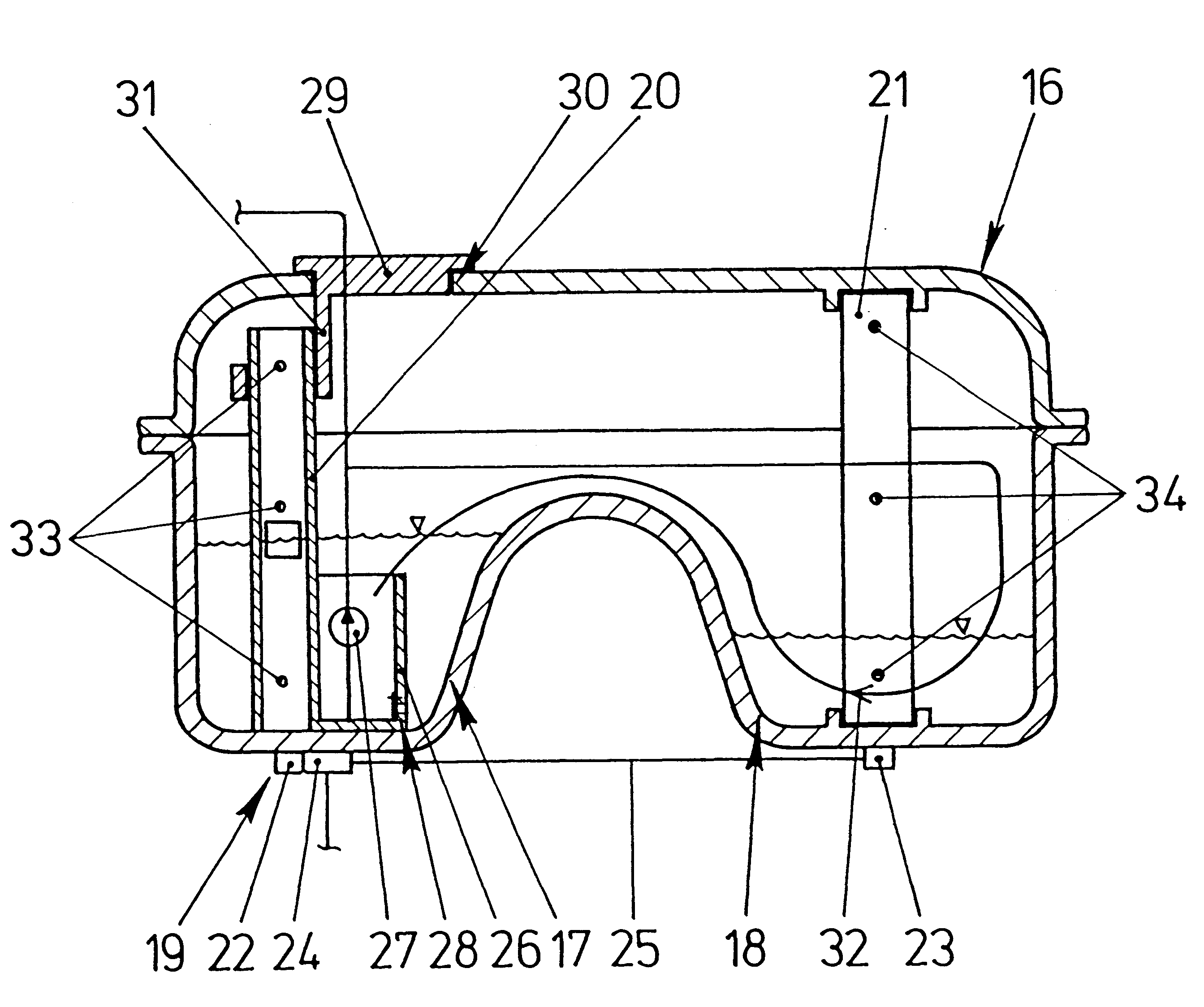
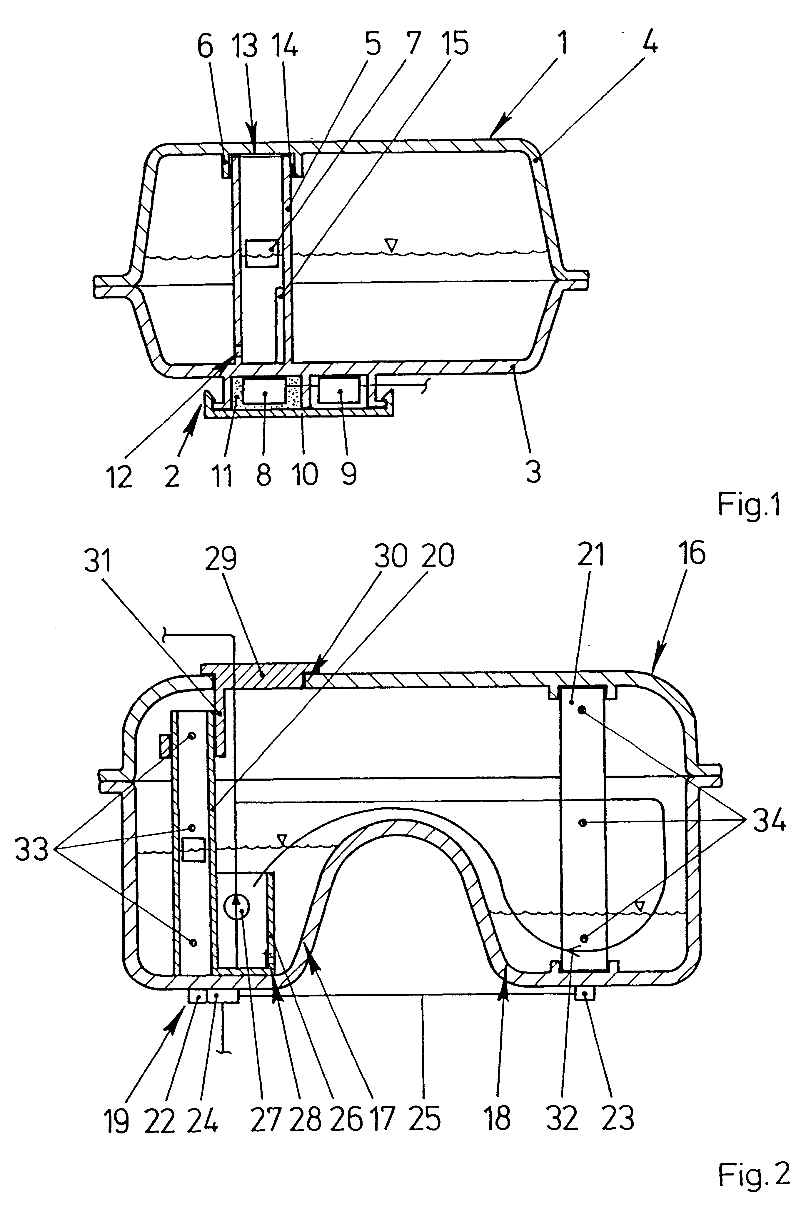
FIG. 1 shows a container 1 with a device 2 for measuring the fill level of liquid in the container 1. The container 1 may, for example, comprise a fuel tank for a motor vehicle and has first and second shell parts 3, 4, i.e., walls, produced from plastic via injection molding and welded to one another. The first shell part 3 is produced in one piece with a measuring tube 5 and the second shell part 4 has support elements 6 for laterally holding the free end of the measuring tube 5. A float 7 is arranged in the measuring tube 5. An ultrasonic sensor 8 and an evaluation unit 9 are arranged on the outside of the container 1 directly below the measuring tube 5 so that a portion of the first shell part 3 is arranged between the measuring tube 5 and the ultrasonic sensor 8. The container 1 has a housing 10 for holding the ultrasonic sensor 8 and the evaluation unit 9. The housing 10 is filled with a contact means 11 in the region of the ultrasonic sensor 8. The contact means 11 is a good ...


PUM


Abstract

A device for measuring a fill level of liquid in a container includes a measuring tube arranged inside the container and an ultrasonic sensor arranged outside the container such that a portion of the wall of the container is arranged between the measuring tube and the ultrasonic sensor. The ultrasonic sensor therefore has no contact with the liquid located in the container.

Description

1. Field of the InventionThe present invention relates to a device for measuring a fill level of a liquid in a container, more specifically in a fuel tank of a motor vehicle. The device comprises a measuring tube with compensating openings and an ultrasonic sensor arranged proximate an end of the measuring tube for generating ultrasonic waves in the measuring tube and for receiving reflections of the ultrasonic waves reflected in the region of the liquid level in the container.2. Description of the Related ArtDevices for measuring the fill level of fuel in a fuel tank using ultrasonic sensors are known in which an ultrasonic sensor has an outside diameter corresponding to the inside diameter of a measuring tube arranged in the fuel tank. The ultrasonic sensor is plugged into an end of the measuring tube. The measuring tube penetrates the bottom of the container and is filled with the liquid present in the fuel tank via compensating bores. To amplify the ultrasonic waves reflected by...

Claims


Application Information

Patent Timeline
Patent Type & Authority Patents(United States)
IPC IPC(8): G01F23/296F02D33/00F02M37/00
CPCF02D33/003G01F23/2962G01F23/2968B60K2015/03118F02M37/0082Y10S367/908F02M37/0094
Inventor KELLER, DIETER
Owner MANNESMANN VDO AG
Why Eureka
Try Eureka