Eureka AIR delivers breakthrough ideas for toughest innovation challenges, trusted by R&D personnel around the world.

Connector assembly for a surgical tool

a technology for connecting parts and surgical instruments, which is applied in the direction of manufacturing tools, metal sawing devices, mechanical devices, etc., can solve the problems of many collets that do not maintain a secure connection between the surgical tool and the housing of the surgical instrument, and the surgical instrument will not be deemed safe and effective,

Inactive Publication Date: 2003-10-28
MICROAIRE SURGICAL INSTR
View PDF13 Cites 39 Cited by
  • Summary
  • Abstract
  • Description
  • Claims
  • Application Information

AI Technical Summary

Benefits of technology

It is a further object of the present invention to provide a connector assembly which properly aligns the surgical tool within the housing of the surgical instrument.
It is still a further object of the present invention to provide a connector assembly which securely locks the surgical tool within the housing of the surgical instrument without any special tools, equipment and the like.
It is also a further object of the present invention to provide a connector assembly which allows a surgeon to easily remove and replace the surgical tool during a surgical procedure.
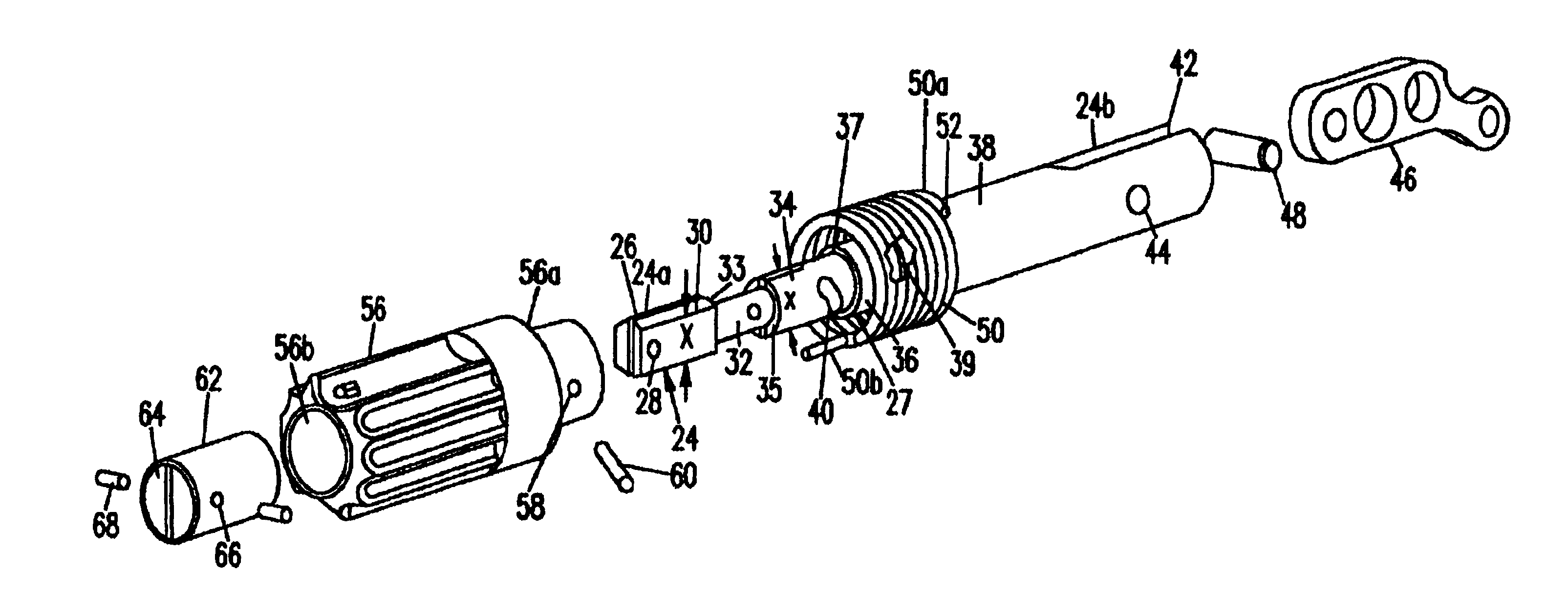
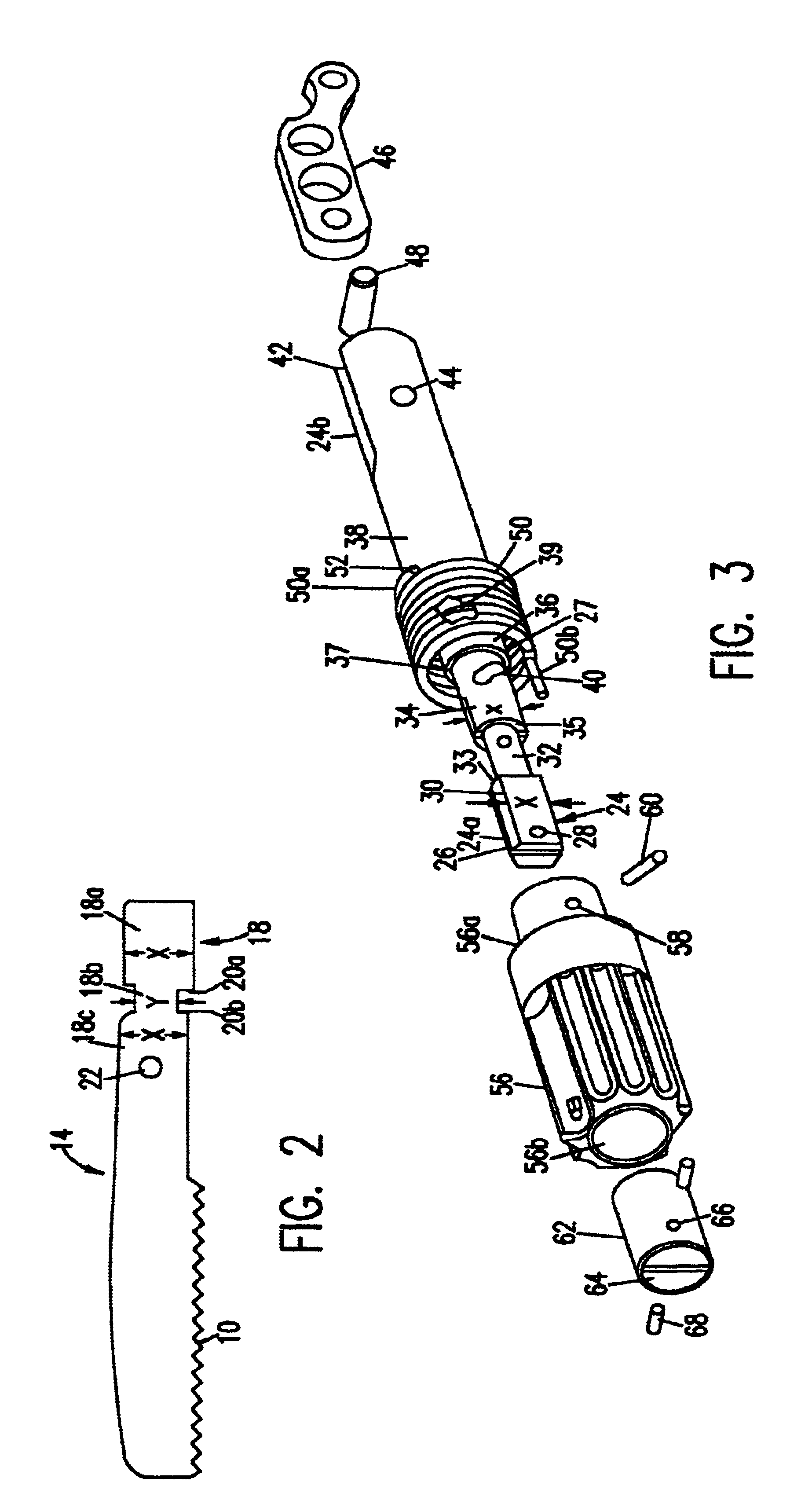
In yet another embodiment, a surgical instrument is provided with a connector assembly. The surgical instrument includes a motor positioned within a housing. A collet is pivotally connected to the motor. The collet is used for connecting a surgical tool to the surgical instrument. The connector assembly includes the collet in addition to a gripper having a centrally located bore. Shelves are formed in the centrally located bore of the gripper which form an elongated slot within the bore of the gripper. The collet includes a longitudinal slot as well as a first section, a second section and a third section. The second section has a different cross section than either of the first section and the second section. A first and second shoulder are formed between the first, second and third sections. The shoulders prevent movement of the gripper when the gripper is biased in a first position.

Problems solved by technology

That is, a surgical instrument will not be deemed safe and effective without a connector assembly which can properly secure the surgical tool to the housing of the surgical instrument.
Although many collets are currently manufactured and sold worldwide for use in surgical instruments, there is certainly concern that many of these collets do not maintain a secure connection between the surgical tool and the housing of the surgical instrument over extended periods of time.
It is also noted that many of these collets can only secure a surgical tool to the housing with cumbersome tools, which have a tendency of breaking or being lost.
In any of these scenarios, the surgical instrument may be rendered useless, thus requiring the disposal of the surgical instrument.
However, these type of collets have a tendency to become "stripped" during the mounting of or removal of the surgical saw blade.
This may pose a severe safety risk to the patient, especially if the surgical saw blade breaks or becomes worn and cannot be removed during a surgical procedure.
The loosening or dislodgement of the surgical tool may also be the result of an overused or deteriorated collet, or simply due to the force applied by the surgeon on the surgical instrument during the surgical procedure.
Regardless of cause, such loosening or dislodgement of the surgical tool from the surgical instrument certainly poses a serious risk to the patient during a surgical procedure.
However, the design of these type of spring loaded systems permit the surgical saw blade to be accidently ejected therefrom; that is, these spring loaded systems have a tendency to permit the surgeon to accidently "hit" the spring loaded release mechanism during use thereof.
In this case, the surgical tool will spontaneously eject from the surgical instrument posing serious injury to both the surgeon and the patient.

Method used


Image

  • Connector assembly for a surgical tool
  • Connector assembly for a surgical tool
  • Connector assembly for a surgical tool

Examples


Embodiment Construction

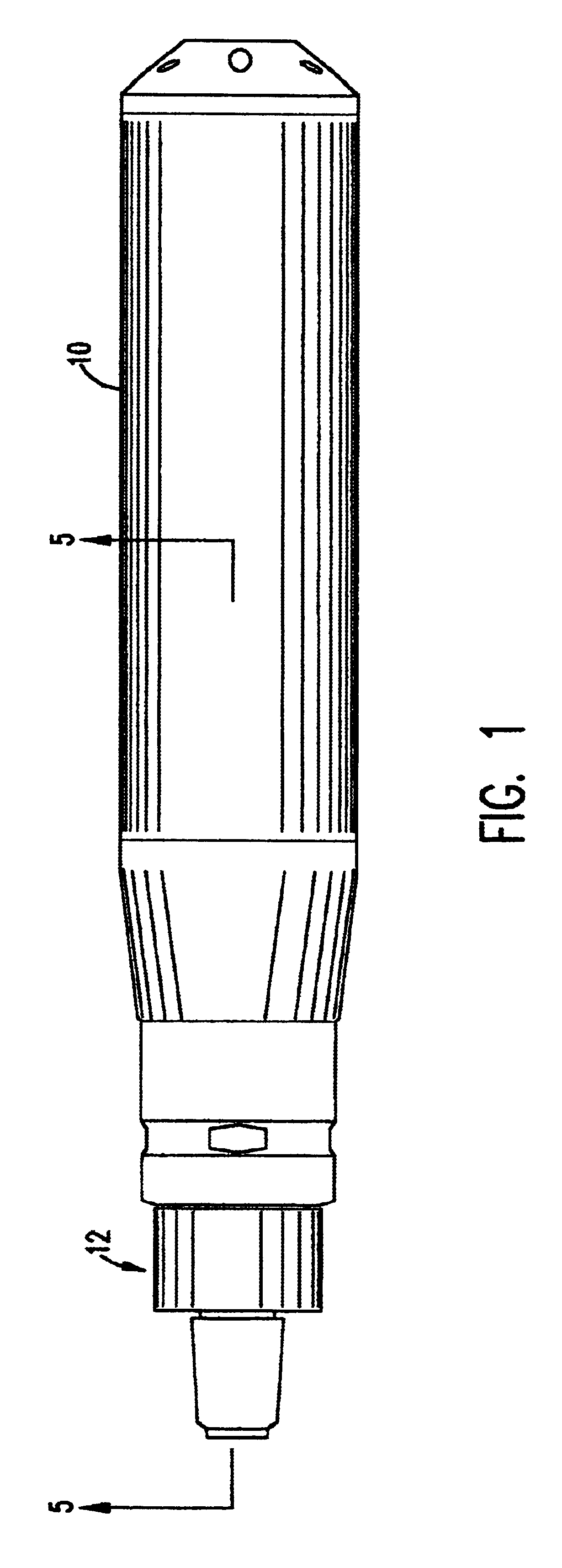
The present invention is directed to a connector assembly for connecting a surgical saw blade to a housing of a surgical instrument. The connector assembly is a keyless system and is capable of connecting several types of surgical saw blades including, for example, a sternum surgical saw blade, to the housing of the surgical instrument. By using the connector assembly of the present invention, a surgeon or other medical personnel can easily align, insert and lock the surgical blade in the connector assembly of the surgical instrument without any special tools, equipment and the like. This enables the surgeon or other medical personnel to easily remove and replace the surgical saw blade during a surgical procedure. The connector assembly of the present invention also provides a stable and robust platform for mounting of the surgical saw blade, while ensuring that the surgical saw blade will remain firmly secured within the housing of the surgical instrument during a surgical procedur...


PUM

PropertyMeasurementUnit
lengthaaaaaaaaaa
movementaaaaaaaaaa
circumferenceaaaaaaaaaa

Abstract

A connector assembly for connecting a surgical saw blade to a housing of a surgical instrument. The connector assembly allows a surgeon to align, insert and lock the surgical blade in the collect of the surgical instrument without any special tools, and further provides a stable and robust platform for mounting the surgical saw blade thereto. The connector assembly includes a gripper having a centrally located bore and a pair of opposing shelves. A shaft having shoulders is slidably fitted within the bore of the gripper. The shoulders communicate with ledges of the shelves to prohibit movement of the finger gripper. This same mechanism also prevents movement of a surgical saw blade, once inserted within the slot of the shaft, from becoming dislodged or ejected from the connector assembly. A biasing spring biases the gripper in a first position, but the gripper can move between the first position and a second position.

Description

1. Field of the InventionThe present invention relates generally to a connector assembly for a surgical instrument and, more particularly, to a connector assembly for securing a surgical tool to a housing of a surgical instrument.2. Background DescriptionConnector assemblies in surgical instruments play an important role in the efficacy and safety of the surgical instrument. That is, a surgical instrument will not be deemed safe and effective without a connector assembly which can properly secure the surgical tool to the housing of the surgical instrument. It is with this in mind that manufacturers of surgical instruments give the utmost attention and care to the design and manufacture of connector assemblies.Connector assemblies are typically referred to as collets and are designed to lock the surgical tool within the housing of the surgical instrument. Although many collets are currently manufactured and sold worldwide for use in surgical instruments, there is certainly concern th...

Claims


Application Information

Patent Timeline
Patent Type & Authority Patents(United States)
IPC IPC(8): A61B17/14B23D51/10B23D51/00
CPCA61B17/14A61B17/148B23D51/10Y10T279/17504A61B17/144
Inventor PASCALOFF, JOHNVENTURA, JOSEPH
Owner MICROAIRE SURGICAL INSTR
Why Eureka
Eureka Blog
Learn More