Hybrid water heater with electrical heating unit and combustor

a hybrid water heater and electric heating technology, applied in the direction of stoves or ranges, applications, ways, etc., can solve the problems of complex system structure of the combined water heater, deficiency of hot water in the hot water tank,

Inactive Publication Date: 2003-10-28
DENSO CORP
View PDF12 Cites 43 Cited by
  • Summary
  • Abstract
  • Description
  • Claims
  • Application Information

AI Technical Summary

Benefits of technology

According to the present invention, in a hybrid water, an electrical heating unit and a combustion heating unit are disposed to heat water to be stored in a hot water tank. The combustion heating unit includes a combustor for heating water in a chamber. The chamber has a first water port at an upper side, through which heated water flows from the camber into an upper side in the hot water tank, and a second water port at a lower side, through which water at a lower side in the hot water tank flows into the camber. In the hybrid water heater, the hot water tank and the chamber are disposed to communicate with each other through the first water port and the second water port, in such a manner that the water heated in the chamber is stored in the hot water tank at the upper side using natural convection due to a temperature increase of the water in the chamber. Accordingly, even in such a condition where hot water deficiency occurs when only using the electrical heating unit, hot water heated by the combustor in the camber can be stored in the hot water tank at the upper side. Therefore, the hot water deficiency can be effectively prevented without particularly enlarging the size of the hot water tank. Further, the high-temperature hot water due to the gas combustion flows into the hot water tank at the upper side using the natural convection. Therefore, a control valve and the like, for switching a hot water circuit between the electrical heating unit and the combustion heating unit, is not required, thereby simplifying an entire system structure of the hybrid water heater. Furthermore, in the hot water tank, the high-temperature hot water is not mixed with low-temperature water at the lower side, and is stored at the upper side. Therefore, the high-temperature hot water due to the gas combustion can be effectively used for a supply.

Problems solved by technology

However, in the electrical water heater, when a large amount of hot water is used at one time, the amount of hot water in the hot water tank may be deficient.
On the other hand, in the combined water heater, because a combustion heating unit using a combustor is simply combined with the electrical water heater, an entire system structure of the combined water heater becomes complex.

Method used


Image

  • Hybrid water heater with electrical heating unit and combustor
  • Hybrid water heater with electrical heating unit and combustor
  • Hybrid water heater with electrical heating unit and combustor

Examples


first embodiment

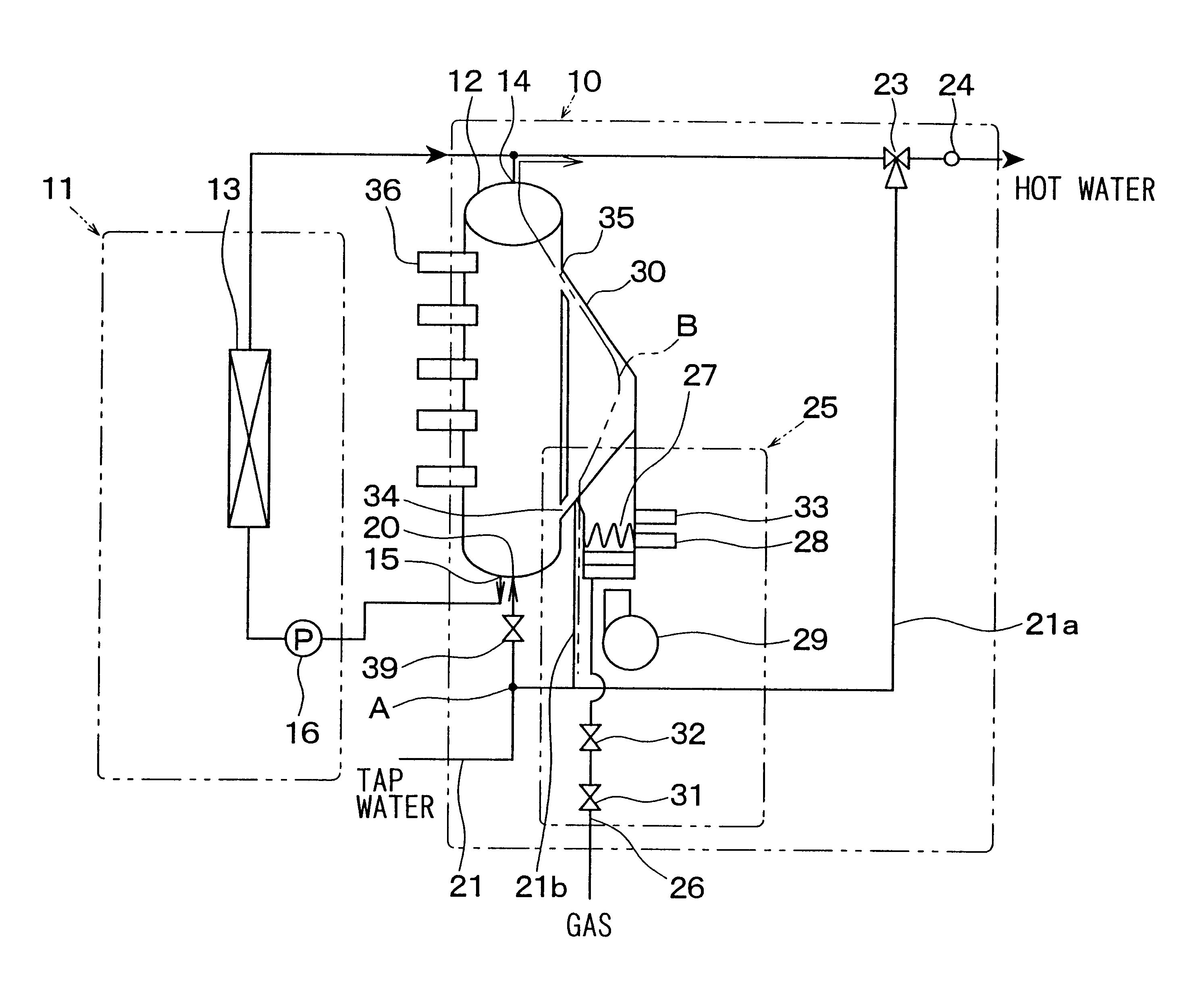
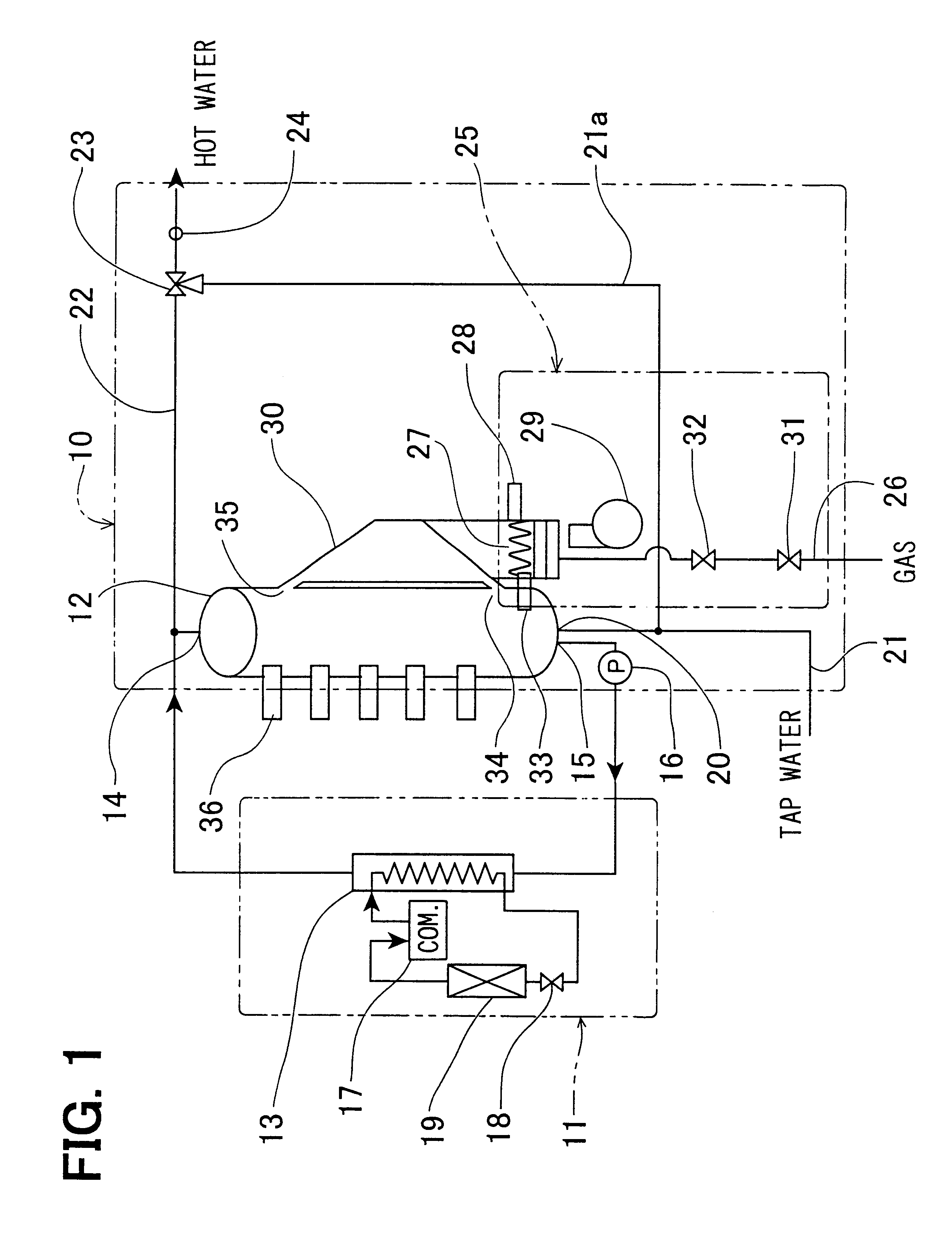
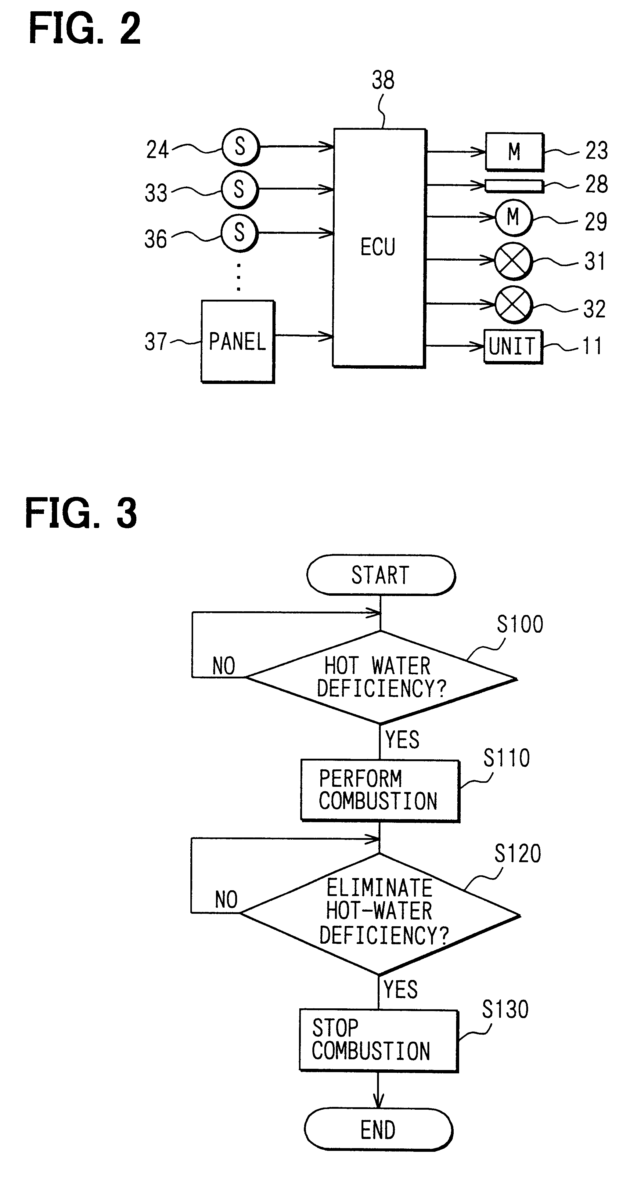
the present invention will be now described with reference to FIGS. 1-3. In the first embodiment, a hybrid water heater according to the present invention is typically used for a home water heater. As shown in FIG. 1, the hybrid water heater is constructed by a hot-water tank unit 10 and a heat pump unit 11. The hot-water tank unit 10 includes a hot water tank 12 extending in a vertical direction (up-down direction). High-temperature hot water, heated by a high-pressure side heat exchanger (radiator) 13 of the heat pump unit, flows into the hot water tank 12 from a hot water port 14 provided on a top portion of the hot water tank 12. Low-temperature water flows into the radiator 13 from a water outlet port 15 provided on a bottom portion of the hot water tank 12, by operation of an electrical pump 16.

In the heat pump unit 11, high-pressure refrigerant, compressed by an electrical compressor 17, flows into the radiator 13, and the high-pressure refrigerant is heat-exchanged with low-...

second embodiment

the present invention will be now described with reference to FIG. 4. In the second embodiment, as shown in FIG. 4, a hot water supply to a hot-water supply equipment such as a bathroom (e.g., bathtub) is controlled. Here, the hot-water supply equipment is connected to the hot water pipe 22 at a downstream side of the temperature adjusting valve 23. In the second embodiment, first, it is determined whether or not a hot-water supply switch (not shown) provided on the operation panel 37 is turned on at step S200. For example, the supply switch is a bath automatic switch for commanding a supply of hot water to the bathtub. When the hot-water supply switch is turned on, it is determined whether or not the hot water in the hot water tank 12 is in a supply capable state at step S210. That is, at step S210, it is determined, based on the temperature distribution in the hot water tank 12, whether or not the amount of hot water having a necessary temperature, commanded by a user, can be supp...

third embodiment

the present invention will be now described with reference to FIG. 5. As shown in FIG. 5, in the third embodiment, the hot water to be supplied is controlled when a target temperature of hot water to be supplied is a high temperature higher than the temperature of the hot water stored at the upper side in the hot water tank 12. The command for supplying the high-temperature hot water is performed using a target temperature setting switch (not shown) provided on the operation panel 37. First, at step S300, it is determined whether the high-temperature hot water (e.g., 80.degree. C.) is commanded using the target temperature setting switch at step S300. When a supply of the high-temperature hot water is not commanded, the control program shown in FIG. 5 is not performed.

When this determination at step S300 is YES, that is, when it is determined that a supply of the high-temperature hot water is commanded at set S300, it is determined whether or not the hot water having the commanded t...


PUM


Abstract

In a hybrid water heater, a heat pump unit and a combustion heating unit are combined for heating water to be stored in a hot water tank. The combustion heating unit includes a combustor for heating water in a chamber by combustion operation. The chamber of the combustion heating unit communicates with the hot water tank through a first water port provided at an upper side of the hot water tank and a second water port provided at a lower side of the hot water tank, so that hot water heated in the chamber flows into the upper side in the hot water tank through the first water port, by using natural convection. Further, water in the hot water tank at the lower side flows from the second water port into the chamber.

Description

This application is related to and claims priority from Japanese Patent Applications No. 2001-106406 filed on Apr. 4, 2001 and No. 2001-359585 filed on Nov. 26, 2001, the contents of which are hereby incorporated by reference.1. Field of the InventionThe present invention relates to a hybrid water heater in which a combustor for heating water is combined with an electrical heating unit having a hot water tank.2. Description of Related ArtAs a conventional water heater, an electrical water heater or a combined water heater is used. In the electrical water heater, water is heated by an electrical heating member, and the heated water (hot water) is stored in a hot water tank while its temperature is maintained. However, in the electrical water heater, when a large amount of hot water is used at one time, the amount of hot water in the hot water tank may be deficient. Accordingly, it is necessary to enlarge the hot water tank, for preventing the hot water in the hot water tank from bein...

Claims


Application Information

Patent Timeline
Patent Type & Authority Patents(United States)
IPC IPC(8): F24H1/18F24H1/00
CPCF24H1/18F24D2200/04F24D2200/12F24D2200/08
Inventor MURAHASHI, HIDEMINENOMURA, SATOSHI
Owner DENSO CORP
Why Eureka
Try Eureka