
Antenna with improved efficiency

a technology of efficiency and antenna, applied in the direction of resonant antennas, elongated active elements, transmission, etc., can solve the problems of absorbing or inducing radiation in their environment which is wasted for the radio link, wasting a portion of electromagnetic energy absorbed by the user, and not being addressed, so as to improve the efficiency of the link

Inactive Publication Date: 2003-11-04
ALCATEL LUCENT SAS
View PDF12 Cites 3 Cited by
  • Summary
  • Abstract
  • Description
  • Claims
  • Application Information

AI Technical Summary

Benefits of technology

This configuration significantly reduces electromagnetic radiation and current-induced losses, enhancing the radio link efficiency by minimizing energy absorption and reradiation towards the user's head, while maintaining effective operation across multiple frequency bands.

Problems solved by technology

The user's head intercepts some of the radiation that could be beneficial to the quality of the radio link; also, electrical currents flow in the casing of the telephone and in the antenna and the proximity of the casing to the head means that these currents are absorbed or induce radiation in their environment which is wasted for the radio link.
From the point of view of the function of the portable telephone, which is to provide efficient radio transmission, the portion of the electromagnetic energy absorbed by the user is wasted.
They do not address the currents which flow when in use in the casing and which degrade the link.
This leads to a corresponding increase in the currents or voltages in the casing.
This further reduces the efficiency of the link.

Method used


Image

  • Antenna with improved efficiency
  • Antenna with improved efficiency
  • Antenna with improved efficiency

Examples


Embodiment Construction

In the remainder of the description, the invention is described in a preferred application to portable telephones for mobile networks. It applies more generally to other types of transceivers.

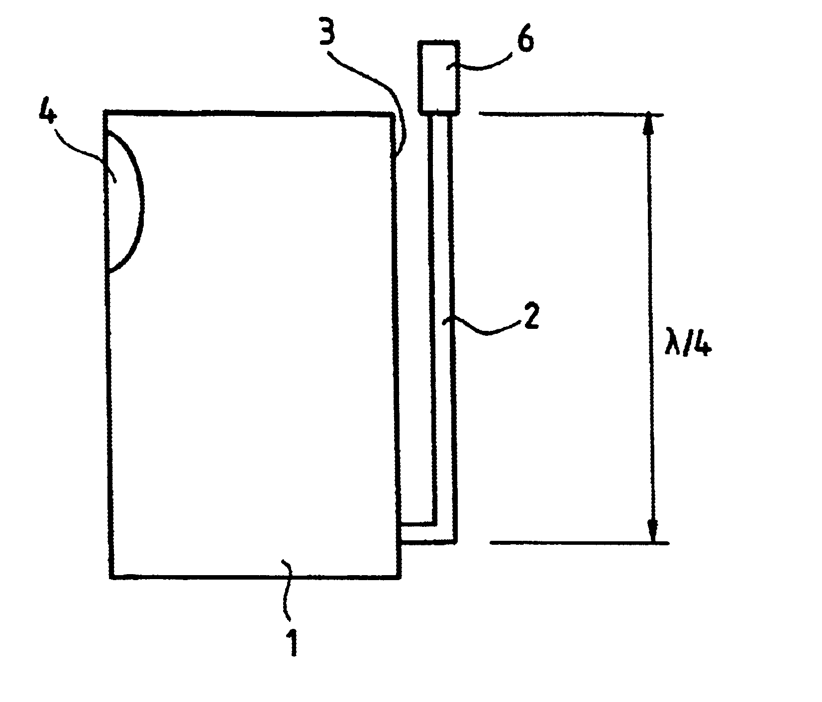
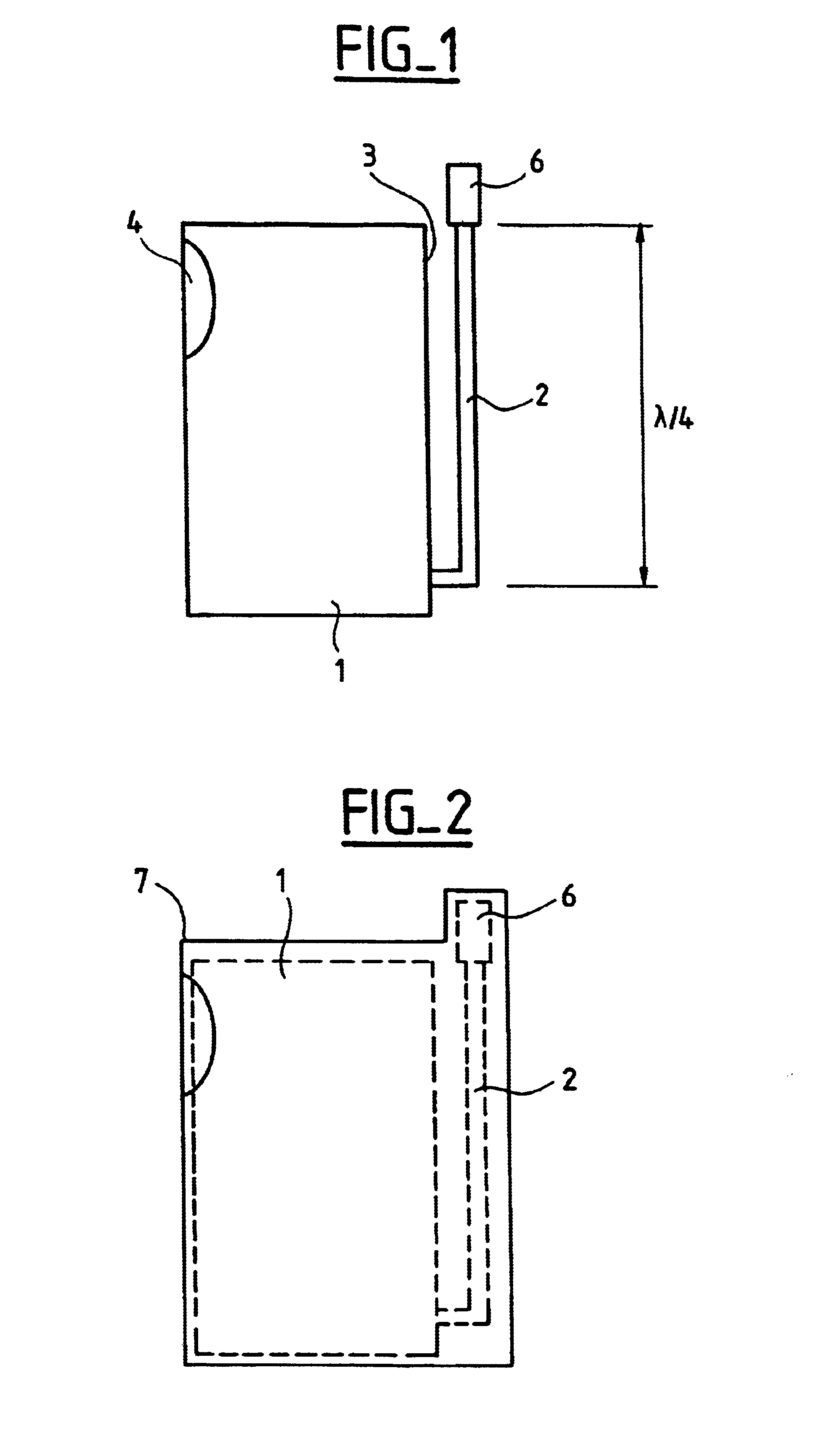
To limit the currents transmitted by the casing, the invention proposes that the antenna be disposed on a support mounted on the casing and whose length is close to one quarter-wavelength. The quarter-wave support acts as a quarter-wave trap and limits the currents in the casing.

FIG. 1 is a diagrammatic representation of a transceiver according to the invention in the example of a public mobile network transceiver (portable telephone). In the example shown in FIG. 1, the telephone has a casing 1 containing the telephone circuits, a loudspeaker and a microphone, a keypad, a display, and a device for receiving a subscriber identification module, for example a SIM or micro-SIM type integrated circuit card. In other words, the casing includes the standard functional units of a portable telephone wi...


PUM


Abstract

A transceiver, which may be a telephone for mobile networks, includes a metal or screened casing, an antenna support mounted on the casing at one end of the antenna support, and an antenna mounted on the other end of the antenna support. The antenna support has a physical or electrical length substantially equal to one quarter of the wavelength of waves emitted by the antenna. The transceiver has improved link efficiency.

Description

The present invention relates to antennas and more precisely to antennas for transceivers of the portable telephone type.Portable telephones, designed to be used as terminals of mobile networks or to communicate with a fixed terminal, include an antenna which is fixed to the casing of the telephone and which is used to transmit radio messages to or from the portable telephone. In conventional use, the portable telephone is near the mouth and the ear. The user's head intercepts some of the radiation that could be beneficial to the quality of the radio link; also, electrical currents flow in the casing of the telephone and in the antenna and the proximity of the casing to the head means that these currents are absorbed or induce radiation in their environment which is wasted for the radio link. Earlier proposed solutions usually relate to the antenna and not to the currents which flow in the casing, even though they can represent the greater part of the energy wasted.From the point of...

Claims


Application Information

Patent Timeline
Patent Type & Authority Patents(United States)
IPC IPC(8): H01Q1/24H01Q9/30H01Q9/04H04B1/03H04B1/38H04B1/02H04B1/08H04M1/03H04Q7/20H04Q7/32
CPCH01Q1/243H01Q1/242
Inventor BARO, JOSE MARIE
Owner ALCATEL LUCENT SAS
Learn More