Tool holder with coolant tube

a tool holder and coolant tube technology, applied in the field of coolant tubes, can solve the problems of repeated problems, reduced coolant pressure, and insufficient push of coolan

Inactive Publication Date: 2003-11-18
CHIRON WERKE
View PDF4 Cites 36 Cited by
  • Summary
  • Abstract
  • Description
  • Claims
  • Application Information

AI Technical Summary

Benefits of technology

The insert tube, which preferably runs through the coolant tube in its complete length, diminishes the clear width of the coolant conduit, so that it was originally assumed that the pressure applied to the cover was enforced and, thus, the danger of malfunction increased. In contrast, it turned out, however, that this was not the case. It turned out, namely, that, via the insert tube, a distinctively better support of the cover can be achieved, which now e.g. can be inserted between the upper end of the coolant tube and the insert tube, so that a toothed ring is not necessary any more.
Said measure is known per se, it ensures that on the outer side, i.e. facing the supply tube, a finer sieve rests, which even filters finest chips, and which is supported by a coarser sieve, so that it does not bend to the inside even when there is heavily pulsating coolant or clogging occurs.

Problems solved by technology

In machine tools, problems repeatedly occur in connection with the supply of coolant to the tools.
Coolant supply is often interrupted by clogged coolant conduits in the tools themselves or influenced disadvantageously by the fact that the seal between the coolant tube and the coolant delivery system on the machine tool becomes leaky, so that coolant pressure declines and is no longer sufficient to push coolant into the small coolant conduits in the tools.
A diminution in the coolant supply due to clogged coolant conduits or a leaking seal often leads, however, to overheating and thus to damage of the tool, so that frequent cleaning of the holder, the coolant tube, and the tools with which the holders are fitted, is necessary.
In operation, it turned out that due to wrong mounting or the pulsating coolant the toothed ring falls out or the sieve is jackknifed, so that the desired protection effect gets lost.
Moreover, it was realized that the sieve is dissolved which also results in a loss of the protection effect.
It has turned out, however, that here, too, the toothed ring falls out or due to mounting problems the insert and / or the toothed ring are wrongly inserted or get lost already on transport, so that the desired protection effect is not reached.
The insert tube, which preferably runs through the coolant tube in its complete length, diminishes the clear width of the coolant conduit, so that it was originally assumed that the pressure applied to the cover was enforced and, thus, the danger of malfunction increased.
In contrast, it turned out, however, that this was not the case.
Since the coolant tube is now completely interspersed by an insert tube, the clear width of the coolant conduit is reduced on the whole length of the coolant tube compared with the prior art, which, however, against all expectations, has neither resulted into problems.
If the tube, however, is run without counter pressure, so to speak in no-load operation, the transporting capacity is distinctively diminished by the insert tube additionally provided, what, originally, seemed to be against the use of such an insert tube.
In that way, wrong mounting is not possible any more, because, if the cover gets jammed in the coolant tube, the insert tube cannot be inserted any more, and that means that the coolant tube cannot be fixed to the tool holder.
Should problems arise while mounting of the sieve on the insert tube for the reason that the sieve gets jammed, the flanging would not be sufficiently possible.
Even if said failure is not realized during the manufacturing of the insert tube equipped with the sieve, it will be realized at the latest when the insert tube is inserted into the coolant tube and cannot be fitted there completely due to lacking of flanging or reversing at its top.

Method used


Image

  • Tool holder with coolant tube
  • Tool holder with coolant tube
  • Tool holder with coolant tube

Examples


Embodiment Construction

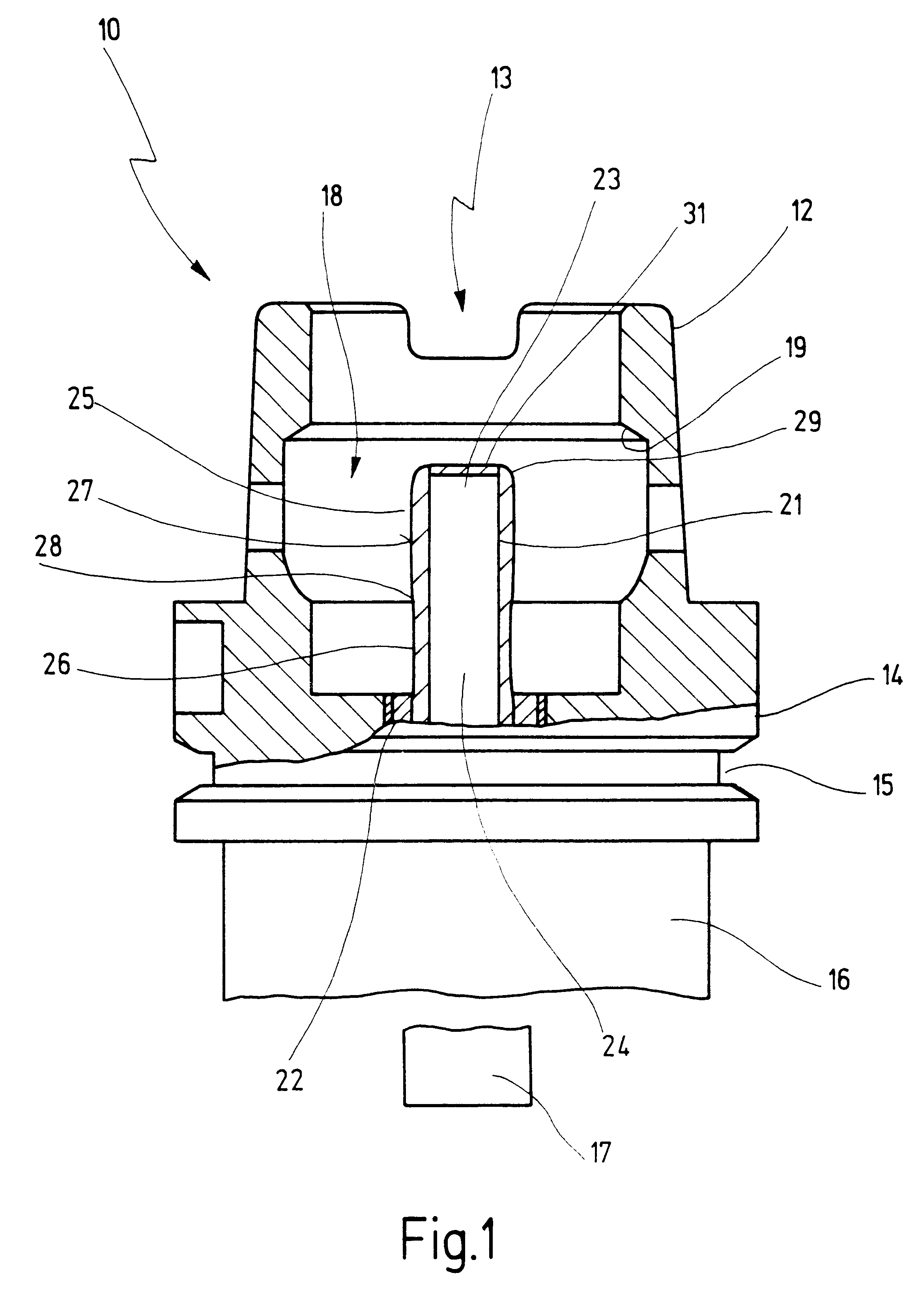
In FIG. 1, 10 designates a holder for a tool that is not shown. The holder is shown in FIG. 1 in a schematic, partly sectioned side view.

Holder 10 has first of all a tapered hollow shaft 12, known per se, in which an upper opening 13 is provided. Adjoining tapered hollow shaft 12 at the bottom is a collar 14, on which an externally circumferential gripper groove 15 for automatic tool changing mechanisms is provided.

Indicated below collar 14 is a holding shaft 16 to which tools 17 can be selectably attached.

Tapered hollow shaft 12 has in its interior 18 a circumferential shoulder 19 that coacts with jaw segments of a clamping system, by means of which holder 10, known to this extent, can be inserted into a tool receptacle in a spindle of a machine tool.

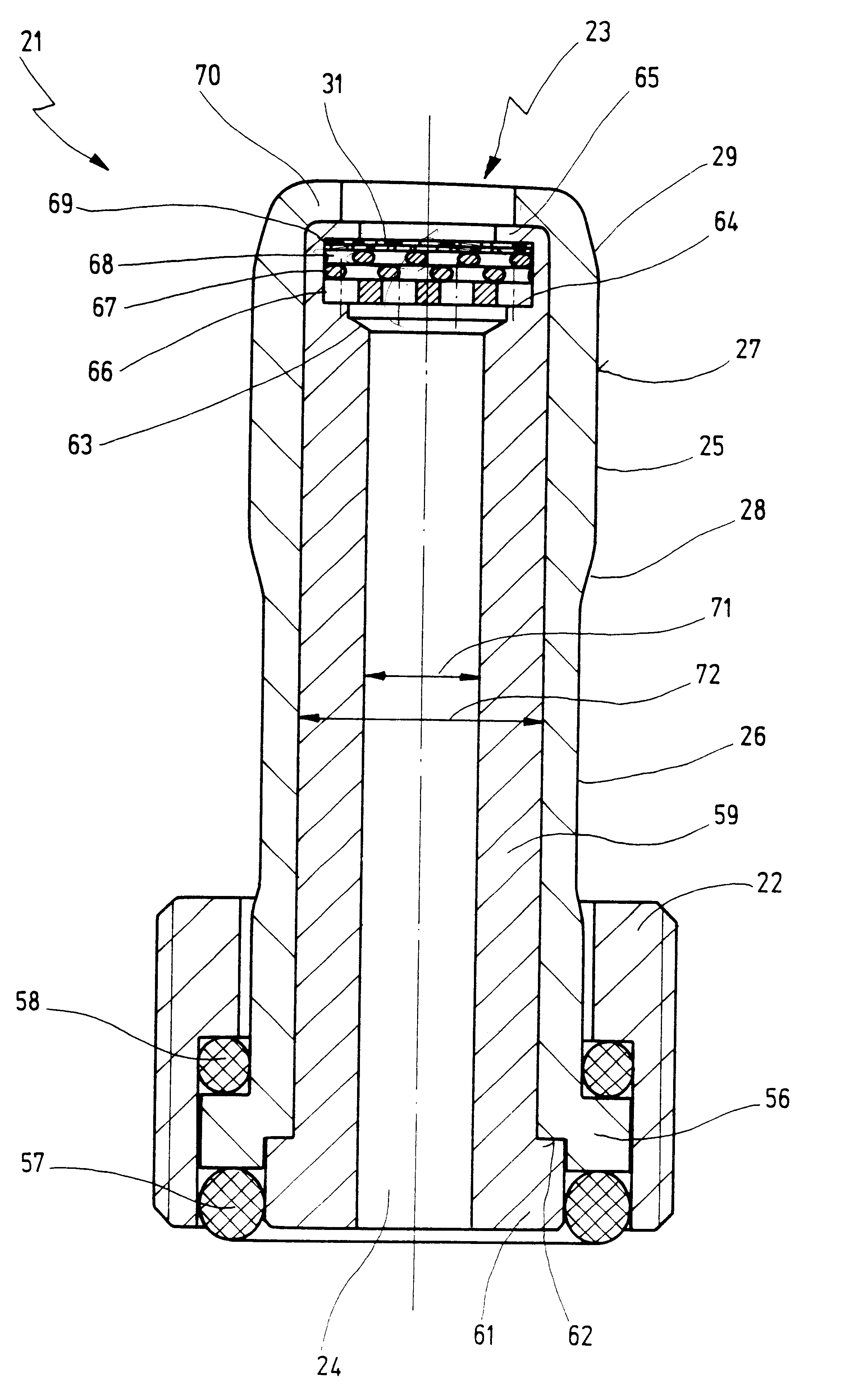
Arranged in interior 18 of tapered hollow shaft 12, in a manner known per se, is a coolant tube 21 that is attached detachably to holder 10 by means of a coupling nut 22. Coolant tube 21 has a coolant conduit 24, opening into an inlet ...


PUM

PropertyMeasurementUnit
diameteraaaaaaaaaa
diameteraaaaaaaaaa
inner diameteraaaaaaaaaa

Abstract

A coolant tube (21) is to be arranged in a tool holder, the coolant tube (21) having an inlet opening (23) for coolants, a cover (31) at the inlet opening (23) for preventing chips from entering into the coolant tube (21), and an exchangeable insert tube (59) arranged within the coolant tube (21) and holding the cover (31).

Description

1. Field of the InventionThe present invention relates to a coolant tube for a holder for a tool having a tapered hollow shaft with an upper opening for clamping into a tool receptacle, wherein the coolant tube is arranged in the interior of the tapered hollow shaft for supply of coolants to the tool, and the coolant tube has an inlet opening for coolants, said inlet opening facing the upper opening, and an upper tube section which, when the holder is clamped in the tool receptacle, projects into a supply tube for coolants, said supply tube overlapping the coolant tube at least partially, whereby a covering is provided for the inlet opening, which prevents chips from entering into the coolant tube.The invention further concerns a holder having a coolant tube of this kind.2. Related Prior ArtSuch a holder with coolant tube is known from DE 196 21 240 A1.These holders, which are also called HSK tool holders, consist substantially of three sections, namely the tapered hollow shaft, adj...

Claims


Application Information

Patent Timeline
Patent Type & Authority Patents(United States)
IPC IPC(8): B23Q11/10B23B29/00B23B29/04B23Q1/00
CPCB23B29/046B23Q1/0018B23Q11/10B23B2250/12Y10T408/455Y10T409/30952Y10T408/45Y10T409/304032B23Q11/1023B23B2231/24
Inventor SCHWEIZER, ANTON
Owner CHIRON WERKE
Why Eureka
Try Eureka