Method for producing a cast strip of molten metal and cast strip

a technology of molten metal and casting roller, which is applied in the field of producing a cast strip of molten metal, can solve the problems of significant mechanical and thermal stress on the outer surface of the casting roller that comes in contact with the molten metal, and achieves the effects of improving the thermal resistance of the surface, reducing the impact force, and improving the impact resistan

Inactive Publication Date: 2019-01-15
OUTOKUMPU NIROSTA
View PDF8 Cites 0 Cited by
  • Summary
  • Abstract
  • Description
  • Claims
  • Application Information

AI Technical Summary

Benefits of technology

[0014]Accordingly, the clear width of the casting gap between the casting rollers varies when the inventive method is carried out. In regions in which a thicker length section should be produced, the casting gap has a greater width, i.e., the circumferential surfaces of the casting rollers that define the width of the casting gap are spaced apart by a greater distance, while the distance between the circumferential surfaces of the casting rollers and therefore also the clear width of the casting gap is reduced in regions in which a thinner length section should be produced. In order to produce length sections of the cast strip that are shifted relative to one another referred to the center plane of the cast strip, i.e., realized asymmetrically in the direction of the thickness of the cast strip, it would be possible, for example, to assign to a circumferential section of one casting roller, which is spaced apart from the rotational axis of the respective casting roller by a greater distance, a circumferential section of the other casting roller, which is spaced apart from the rotational axis of this casting roller by a shorter distance, and vice versa.
[0015]The invention therefore makes it possible to produce a strip that is cast of molten metal and already has the required non-uniform thickness distribution from the time of its creation in one continuous primary forming process. Such a cast strip that has at least two length sections with different thicknesses and is produced in accordance with the invention therefore forms an optimal starting product, for example, for being further processed into components, in which sheet metal sections with different thicknesses are assigned to zones that are subjected to different loads, in order to achieve the required load capacity of the component on the one hand and a minimal weight on the other hand.
[0026]One option for purposefully adapting the heat transfer between the molten metal and the respective circumferential section of the casting roller that can be easily implemented and therefore is significant for practical applications consists of suitably modifying the surface structure of the casting roller in the respective circumferential surface section. For this purpose, it would be possible, for example, that the circumferential surface sections assigned to the length sections of different thickness have a different roughness. The different surface roughness can be adjusted, for example, by means of a suitable peening treatment such as, for example, shot-peening or by means of a suitable application of a coating as described, for example, in DE 10 2007 003 548 B3. The heat flow changes due to the type and the degree of the roughness (Ra, Rz). Layers with a thickness in the range of 100-200 μm that are, in particular, thermally sprayed onto the roller surfaces increase the thermal resistance of the surface and therefore locally reduce the heat flow density. The reasons for this are the low thermal conductivity of the sprayed layer and the higher heat transfer through the highly fissured microtopography.
[0027]According to the invention, the circumferential surface section on the casting roller assigned to the length section with greater thickness may therefore be provided with a suitable topography by means of shot-peening or another surface treatment. The heat transfer from the molten metal into the casting roller generally decreases as the roughness of the circumferential surface of the casting roller coming in contact with the molten metal increases. This means that the circumferential surface section assigned to a length section, in which the cast strip should have a reduced thickness, can accordingly be provided with a greater roughness such that less heat is dissipated into the respective casting roller in this region while the circumferential surface section assigned to a length section of the cast strip with smaller thickness can have a reduced roughness in order to achieve a diminished heat dissipation and therefore a diminished growth of the shell solidifying in this circumferential surface section.
[0028]Alternatively or additionally, the heat transfer between the respective circumferential surface section of the casting roller and the molten metal may also be influenced by applying a coating. Suitable coatings consist, for example, of Fe—Cu—Fe and are applied by means of thermal spraying. Due to the application of a metal layer that decreases or increases the thermal resistance of the respective circumferential surface section, locally different heat flows and therefore different solidification rates are adjusted during the contact of the molten metal with the respective circumferential section. In this case, a coating that allows a greater heat flow from the molten metal into the respective casting roller is also applied onto a circumferential surface section that is assigned to a length section of greater thickness of the cast strip while the coating in a circumferential surface section assigned to a length section of a smaller thickness of the cast strip is realized such that a diminished heat flow and therefore a diminished shell growth occur.

Problems solved by technology

However, the outer surface of the casting rollers that comes in contact with the molten metal is subjected to significant mechanical and thermal stresses in practical applications.

Method used


Image

  • Method for producing a cast strip of molten metal and cast strip
  • Method for producing a cast strip of molten metal and cast strip
  • Method for producing a cast strip of molten metal and cast strip

Examples


Embodiment Construction

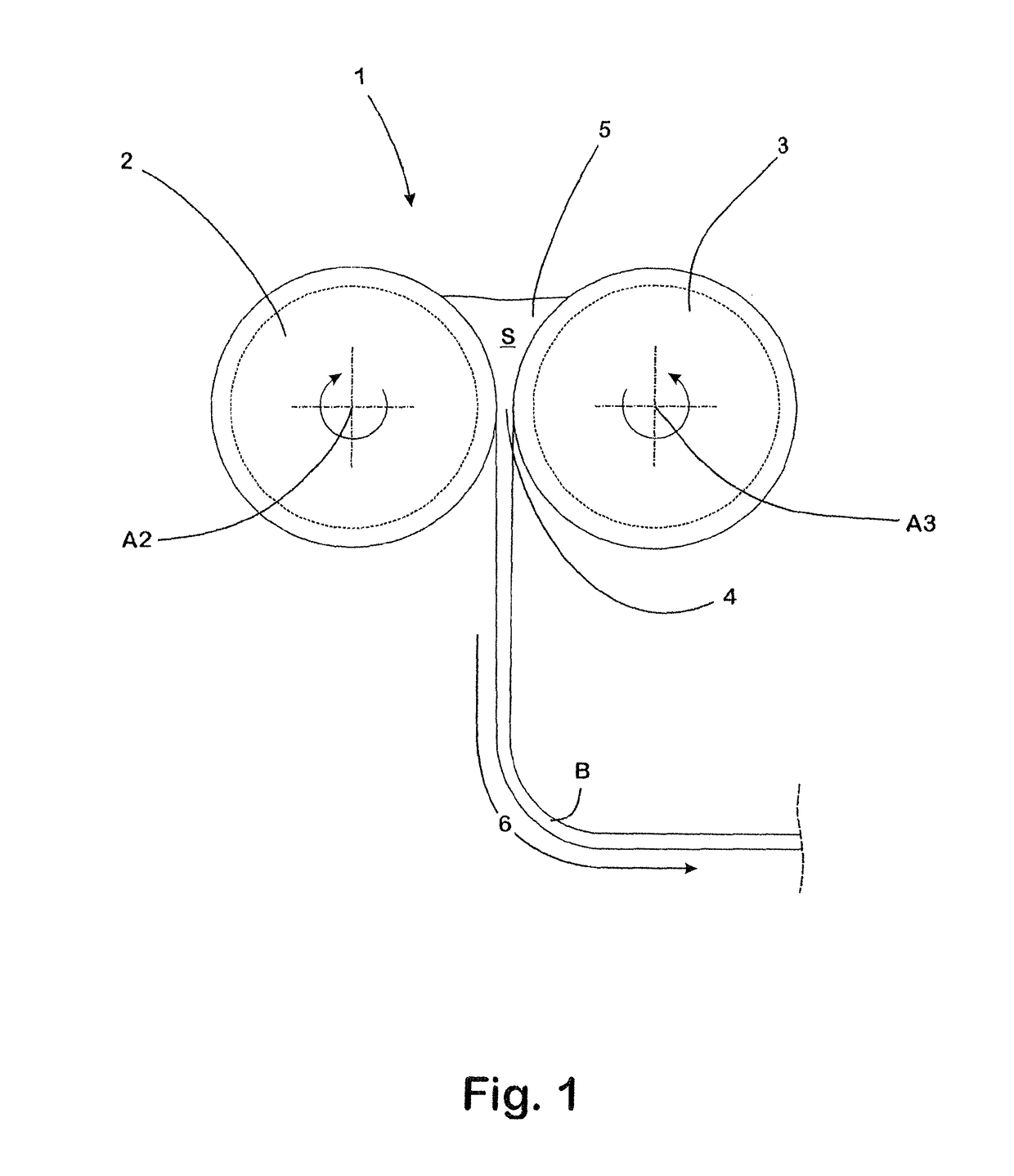
[0045]The twin-roller casting machine 1 illustrated in FIG. 1 serves for casting molten steel S into a cast steel strip B and has, in principle, a conventional design with two casting rollers 2, 3 that are arranged axially parallel to one another and rotate in opposite directions about their rotating axes A2, A3, wherein said casting rollers define the longitudinal sides of a casting gap 4 formed between the casting rollers, as well as of the melt pool 5 that is situated above the casting gap and into which the molten steel S to be cast is introduced. The two lateral narrow sides of the casting gap 4 and of the melt pool 5 are not defined by the casting rollers 2, 3 and respectively sealed by the plate-shaped lateral seals shown.

[0046]The cast steel strip B exiting the casting gap 4 is also conventionally transported away along a transport path 6. Starting at the casting gap 4, the transport path 6 features a first section that essentially extends vertically and then leads to a roll...


PUM

PropertyMeasurementUnit
thicknessaaaaaaaaaa
thicknessaaaaaaaaaa
widthaaaaaaaaaa

Abstract

A method for producing a cast strip of molten metal, in which the molten metal passes through a casting gap defined by two oppositely rotating casting rollers and is shaped into the cast strip, as well as the cast strip that is produced. By providing the cast strip in the casting gap with a different thickness in a first length section extending in the longitudinal direction of the cast strip than in a second length section bordering thereon, a metal strip is produced that has length sections with different thicknesses.

Description

CROSS-REFERENCE TO RELATED APPLICATIONS[0001]This application is the United States national phase of International Application No. PCT / EP2013 / 070275 filed Sep. 27, 2013, and claims priority to German Patent Application No. 10 2012 109 286.9 filed Sep. 28, 2012, the disclosures of which are hereby incorporated in their entirety by reference.BACKGROUND OF THE INVENTIONField of the Invention[0002]The invention pertains to a method for producing a cast strip of molten metal, in which the molten metal passes through a casting gap defined by two oppositely rotating casting rollers and is shaped into a cast strip.Description of Related Art[0003]A method of this type is carried out on a two-roller casting device. When casting molten metals in such devices that are also referred to as “twin-roller casting machines,” two casting rollers that are arranged axially parallel and internally cooled respectively rotate opposite to one another and define the longitudinal sides of a casting gap betwee...

Claims


Application Information

Patent Timeline
Patent Type & Authority Patents(United States)
IPC IPC(8): B22D11/06B22D11/00B22D25/02
CPCB22D25/02B22D11/0682B22D11/0651B22D11/0622B22D11/009
Inventor KLOS, WILFRIEDSCHMITZ, JOHANN WILHELMGRAF, GERHARDDAAMEN, MARKUS
Owner OUTOKUMPU NIROSTA
Why Eureka
Try Eureka