Means for monitoring holding brake wear

Inactive Publication Date: 2003-11-25
MANNESMANN AG
View PDF3 Cites 15 Cited by
  • Summary
  • Abstract
  • Description
  • Claims
  • Application Information

AI Technical Summary

Problems solved by technology

The braking action may be affected by wear and/or by the development of a layer of corrosion on brake disks when the brakes have not been actuated for a long period or have been stopped for a

Method used


Image

  • Means for monitoring holding brake wear
  • Means for monitoring holding brake wear

Examples


Embodiment Construction

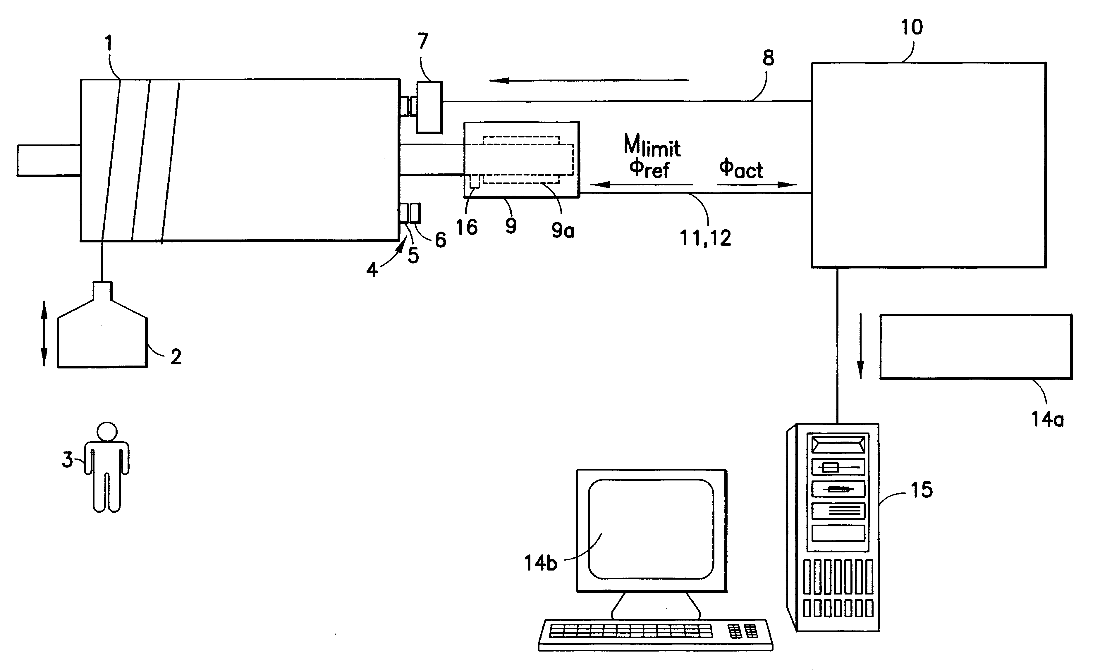
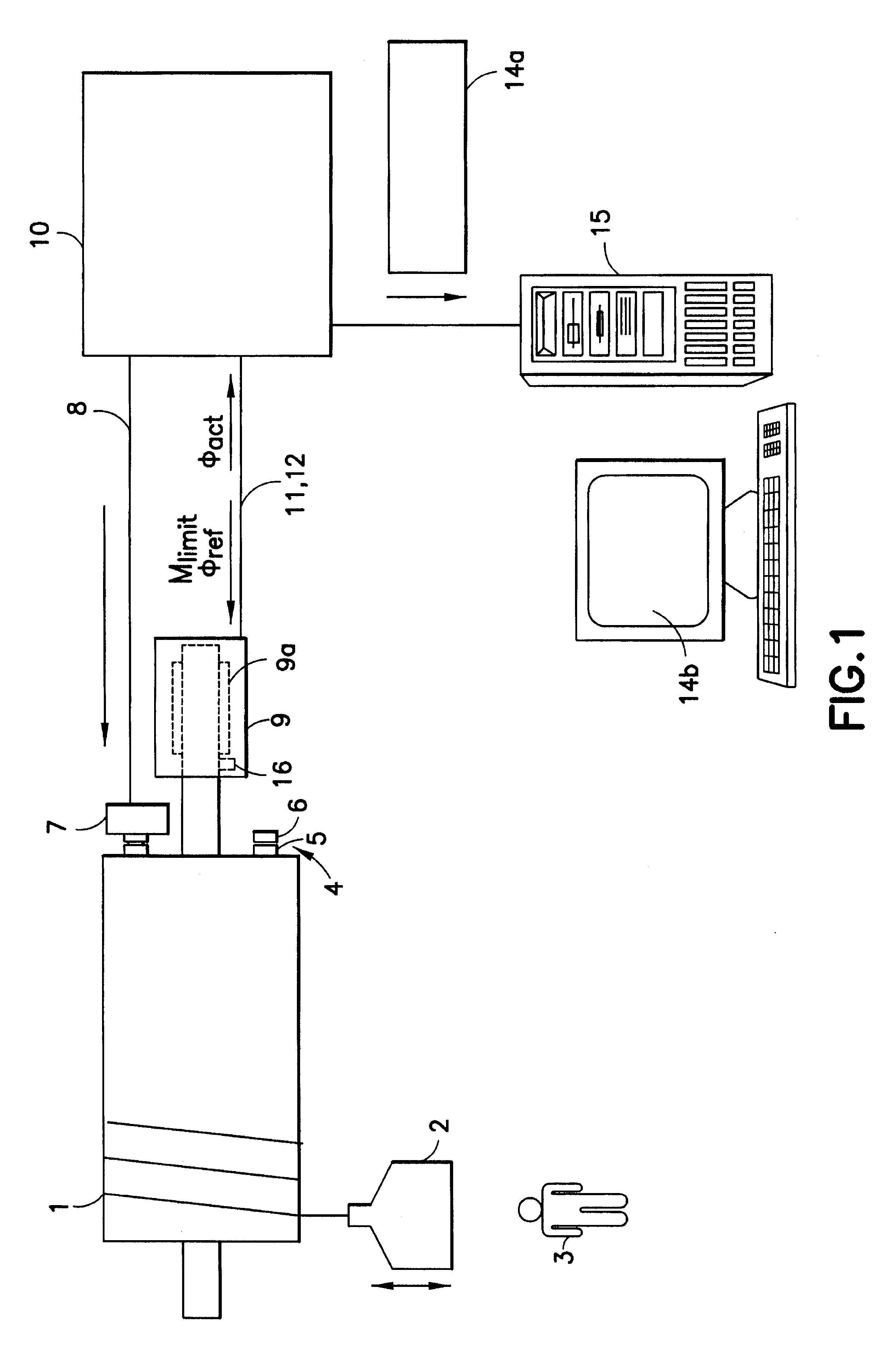
FIG. 1 shows a shaft 1 on which a load 2 is suspended. The load 2 may be respectively raised and lowered by rolling and unrolling a rope which is wound on the shaft 1. The load 2 must be prevented from falling on persons 3 such as workers at a work site who are passing beneath the load 2. A holding brake 4 is arranged for preventing the load 2 from falling by braking the shaft 1 with brake linings 5, 6 which act against one another with adhesive friction for braking. The brake linings 5, 6 are pressed against one another with adhesive friction such as, for example, by a spring or a permanent magnet and may be spread apart by an electromagnet 7 for selectively disengaging the holding brake. The electromagnet 7 is supplied with current via lines 8 for disengaging, i.e., releasing, the holding brake 4.

The shaft 1 is rotatable by a motor 9 against the braking torque of the holding brake when the holding brake is not released and is rotatable as well when the holding brake is released. T...


PUM


Abstract

A highly dependable process and device for monitoring wear for a holding brake is performed via an electronically controlled brake test. A shaft which is drivable by a motor can be braked by the holding brake. A reference angular position which is to be traveled by the motor during the brake test and which deviates from the current actual angular position of the motor is preset along with a maximum limit torque to be applied by the motor during the brake test are preset for the motor. During the brake test, the actual angular position of the shaft is monitored to determine whether the shaft rotates. The existence of wear in the holding brake is evidenced by rotation of the shaft during the brake test.

Description

1. Field of the InventionThe present invention is directed to a method and a device for determining, i.e., detecting, wear in a holding brake which is used for braking a shaft driven by a motor.2. Description of the Related ArtAs a rule, a holding brake comprises an electromagnet which holds a shaft at a standstill via brake disks. That is, the holding brake reliably prevents the rotation of the shaft. For reasons of operating safety, it is imperative that a holding brake of this type brakes with sufficient strength. The braking action may be affected by wear and / or by the development of a layer of corrosion on brake disks when the brakes have not been actuated for a long period or have been stopped for a long time. For safe and reliable operation of the shaft on which the holding brake is arranged, reliable detection of wear is essential.The object of the present invention is to detect wear in a holding brake in the most efficient manner possible and with sufficient dependability.T...

Claims


Application Information

Patent Timeline
IPC IPC(8): F16D65/14F16D66/00F16D66/02F16D55/02G01L5/28
CPCF16D55/02F16D66/02G01L5/28F16D2066/006F16D2121/22F16D2066/003
Inventor HERTERICH, THOMASRUPPEL, WOLFGANGSCHEMM, EBERHARD
Owner MANNESMANN AG
Why Eureka
Try Eureka