Electro-optic display and adhesive composition for use therein

a technology of electro-optic displays and adhesive compositions, applied in the direction of identification means, instruments, static indicating devices, etc., can solve the problems of unsatisfactory commercial pressure sensitive adhesives, inadequate service life of electro-optic displays, and preventing their widespread us

Inactive Publication Date: 2003-12-02
E INK CORPORATION
View PDF119 Cites 506 Cited by
  • Summary
  • Abstract
  • Description
  • Claims
  • Application Information

AI Technical Summary

Problems solved by technology

Nevertheless, problems with the long-term image quality of these displays have prevented their widespread usage.
For example, particles that make up electrophoretic displays tend to settle, resulting in inadequate service-life for these displays.
Unfortunately, there is one requirement for the proper operation of electrophoretic and other electro-optic displays which has not been found to be met by any commercial pressure sensitive adhesive, namely appropriate volume resistivity.
Increasing the voltage across the electrodes in this manner is undesirable, since it increases the power consumption of the display, and may require the use of more complex and expensive control circuitry to generate (in the case of battery-powered portable devices) and / or handle the increased voltage involved.
On the other hand, if the adhesive layer, which extends continuously across the display, is in contact with a matrix of closely-spaced electrodes, such as the pixel electrode arrays used for active matrix displays, the volume resistivity of the adhesive layer should not be too low, or lateral conduction of electric current through the continuous adhesive layer may cause undesirable cross-talk between adjacent electrodes.
Unfortunately, there are grave difficulties in adopting this approach to achieve the volume resistivities of about 10.sup.10 ohm cm required for adhesives used in electro-optic displays.
It is difficult (and may be impracticable under mass production conditions) to control the proportion of filler with sufficient accuracy to maintain the volume resistivity desired in the adhesive.
Furthermore, the variation of resistivity with proportion of filler at this point is so vertiginous that inevitable slight variations in the proportion of filler in particular areas of the display may cause undesirable effects in the display.

Method used


Image

  • Electro-optic display and adhesive composition for use therein
  • Electro-optic display and adhesive composition for use therein
  • Electro-optic display and adhesive composition for use therein

Examples


example 2

This Example illustrates the variation in volume resistivity achieved by adding NeoRez R 9320 (a water-dispersible polyurethane available from NeoResins, 730 Main Street, Wilmington, Mass. 01887) to the aforementioned GME-2417.

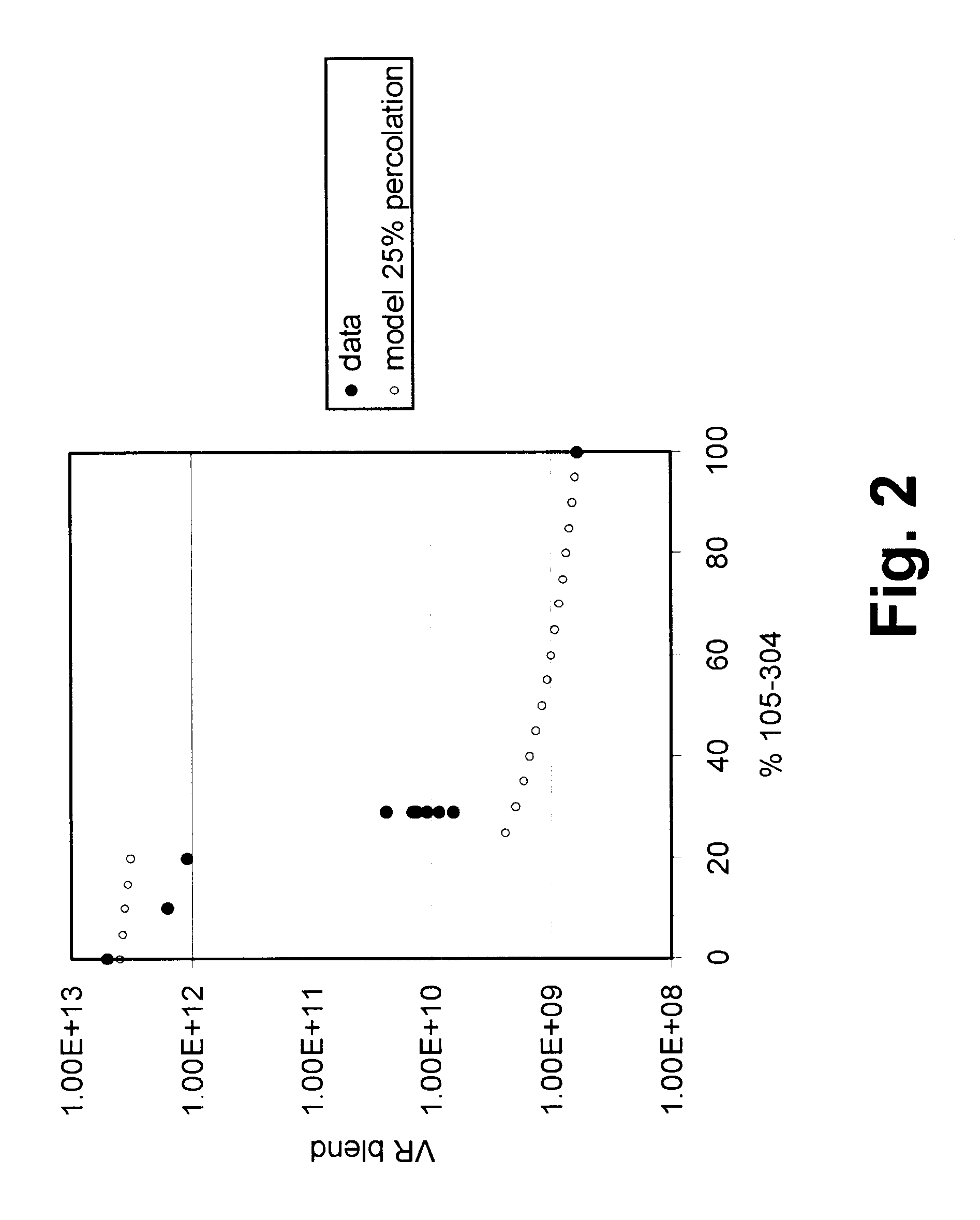
Varying proportions of NeoRez R 9320 were blended with GME-2417 and the volume resistivities of the resultant blends were measured in the same way as in Example 1 above. The results are illustrated in FIG. 3 of the accompanying drawings, which also shows theoretical results calculated assuming a percolation threshold of 20 percent by volume. As in Example 1 above, the experimental results are a reasonably good fit to the model, displaying a sudden drop as the percolation threshold is passed and a slow decrease thereafter as the proportion of filler is increased. It will also be seen that at about 40 percent filler loading, the blend has a volume resistivity of about 3.times.10.sup.10 ohm cm, rendering it suitable for use in lamination of an electro-optic displ...


PUM

PropertyMeasurementUnit
volume resistivityaaaaaaaaaa

Abstract

An electro-optic display comprises first and second substrates, and an adhesive layer and a layer of electro-optic material disposed between the first and second substrates. The adhesive layer has a volume resistivity in the range of about 10<9 >to about 10<11 >ohm cm and comprises a mixture of an adhesive material having a volume resistivity of at least about 5x10<11 >ohm cm and a filler having a volume resistivity not less than about 10<7 >ohm cm, the filler being present in the mixture in a proportion above its percolation threshold in the adhesive material.

Description

BACKGROUND OF INVENTIONThis invention relates to electro-optic displays and to adhesive compositions for use therein. More specifically, this invention relates to adhesive compositions having controlled volume resistivity, and to electro-optic displays incorporating such adhesive compositions. The adhesive compositions of the present invention may also be useful in applications other than electro-optic displays.Electro-optic displays comprise a layer of electro-optic material, a term which is used herein in its conventional meaning in the art to refer to a material having first and second display states differing in at least one optical property, the material being changed from its first to its second display state by application of an electric field to the material. The optical property is typically color perceptible to the human eye, but may be another optical property, such as optical transmission, reflectance, luminescence or, in the case of displays intended for machine reading...

Claims


Application Information

Patent Timeline
Patent Type & Authority Patents(United States)
IPC IPC(8): C09J9/00C09J9/02G02F1/01G02F1/1334G02F1/167G02F1/15G02F1/13C08L33/00C08L83/04C08L75/04C08L75/00C08L83/00G02F1/1339C09J11/04C09J11/06C09J11/08C09J133/00C09J175/04C09J183/04G02F1/16757G09F9/00G09F9/30
CPCG02F1/167C09J11/04C09J11/08G02F1/1334G02F1/15C09J9/02C08L33/00C08L75/04C08L83/00C08L83/04G02F1/16757
Inventor LOXLEY, ANDREW L.
Owner E INK CORPORATION
Why Eureka
Try Eureka