Fabrication of conductive/non-conductive nanocomposites by laser evaporation

a technology of conductive/non-conductive nanocomposites and laser evaporation, which is applied in the field of material deposition, can solve the problems of inability to achieve precise or accurate control of coating thickness with high reproducibility, and the non-uniformity of coatings

Inactive Publication Date: 2003-12-09
THE GOVERNMENT OF THE UNITED STATES OF AMERICA AS REPRESENTED BY THE SEC OF THE NAVY NAVAL RES LAB WASHINGTON
View PDF17 Cites 52 Cited by
  • Summary
  • Abstract
  • Description
  • Claims
  • Application Information

AI Technical Summary

Problems solved by technology

For reasons discussed below, each of these techniques has the disadvantage that after the solvent evaporates, the resulting coatings tend to be non-uniform, lacking in homogeneity and imprecisely located.
However, it is difficult to achieve precise or accurate control of coating thickness with high reproducibility because of the difficulty in duplicating variables such as the cleanliness of the substrate, the viscosity of the solution, temperature conditions, the spin rate of the substrate and the delivery rate of the solution.
Moreover, spin coating and aerosol spray coating are not well suited for coating discrete, micron-sized substrate areas because of the difficulty of using masking with these techniques.
However, this technique provides inadequate control over the physical parameters of the deposit.
Because the placement of matrix material is controlled by the movement and evaporation of solvent molecules on the substrate surface, there is little control over the shape of the resulting polymer-conductor film.
An additional disadvantage of the three "wet" techniques described above is that as the solvent evaporates from a deposit, an increasingly concentrated solution of the composite material is formed, which may result in some degree of phase separation of the conducting and non-conducting material through aggregate formation.
As a result, the conductive material would not be uniformly distributed through the polymeric film when all the solvent evaporated.
Areas of the polymer coating may not have the required quantity or uniform distribution of conductive material to allow electrical conductance.
The resulting performance of a sensor fabricated in this fashion would be significantly impaired.
An increase in non-polar adsorptive properties is undesirable if the polymer properties have been tailored towards sorbing polar analytes.

Method used


Image

  • Fabrication of conductive/non-conductive nanocomposites by laser evaporation
  • Fabrication of conductive/non-conductive nanocomposites by laser evaporation
  • Fabrication of conductive/non-conductive nanocomposites by laser evaporation

Examples


example

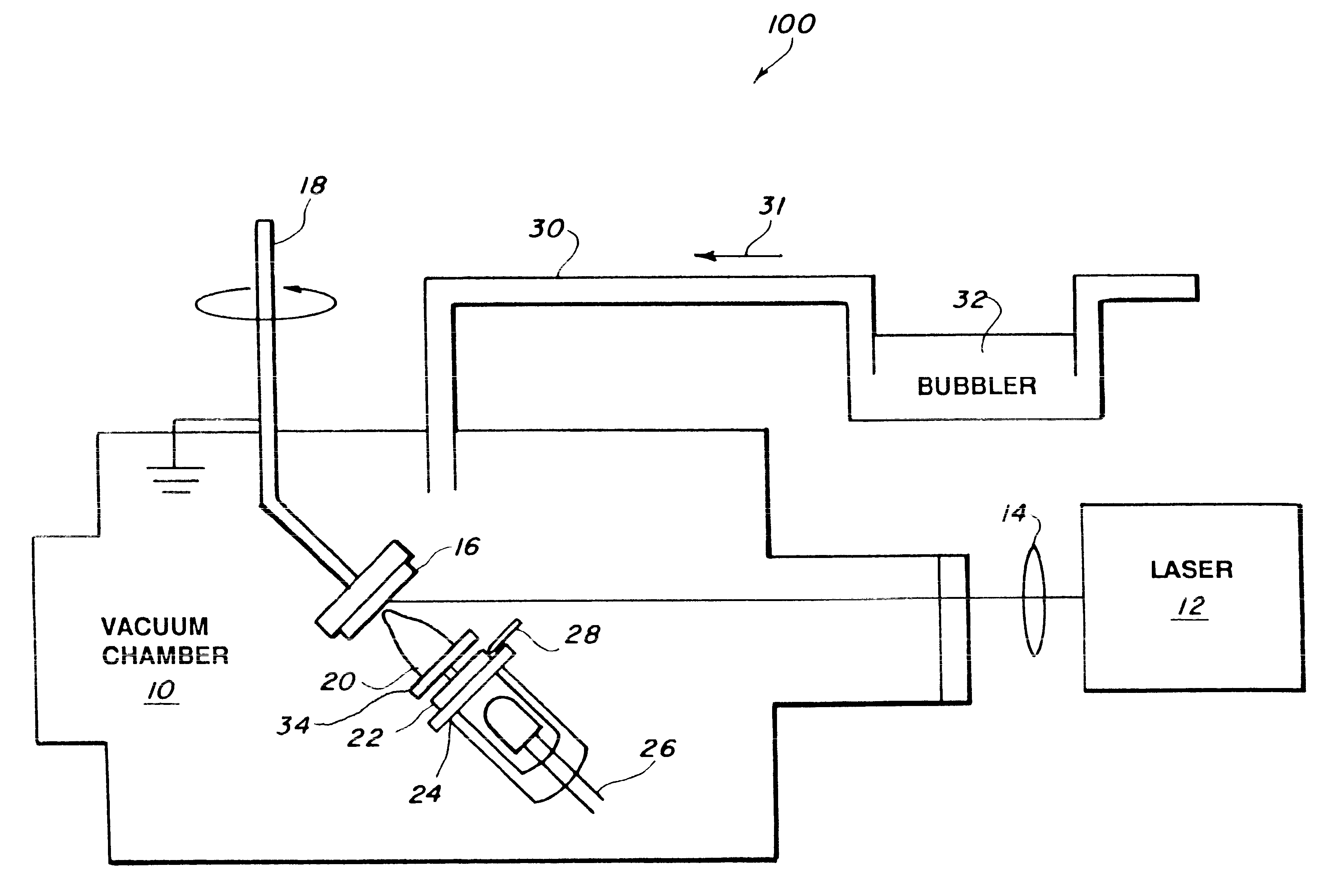
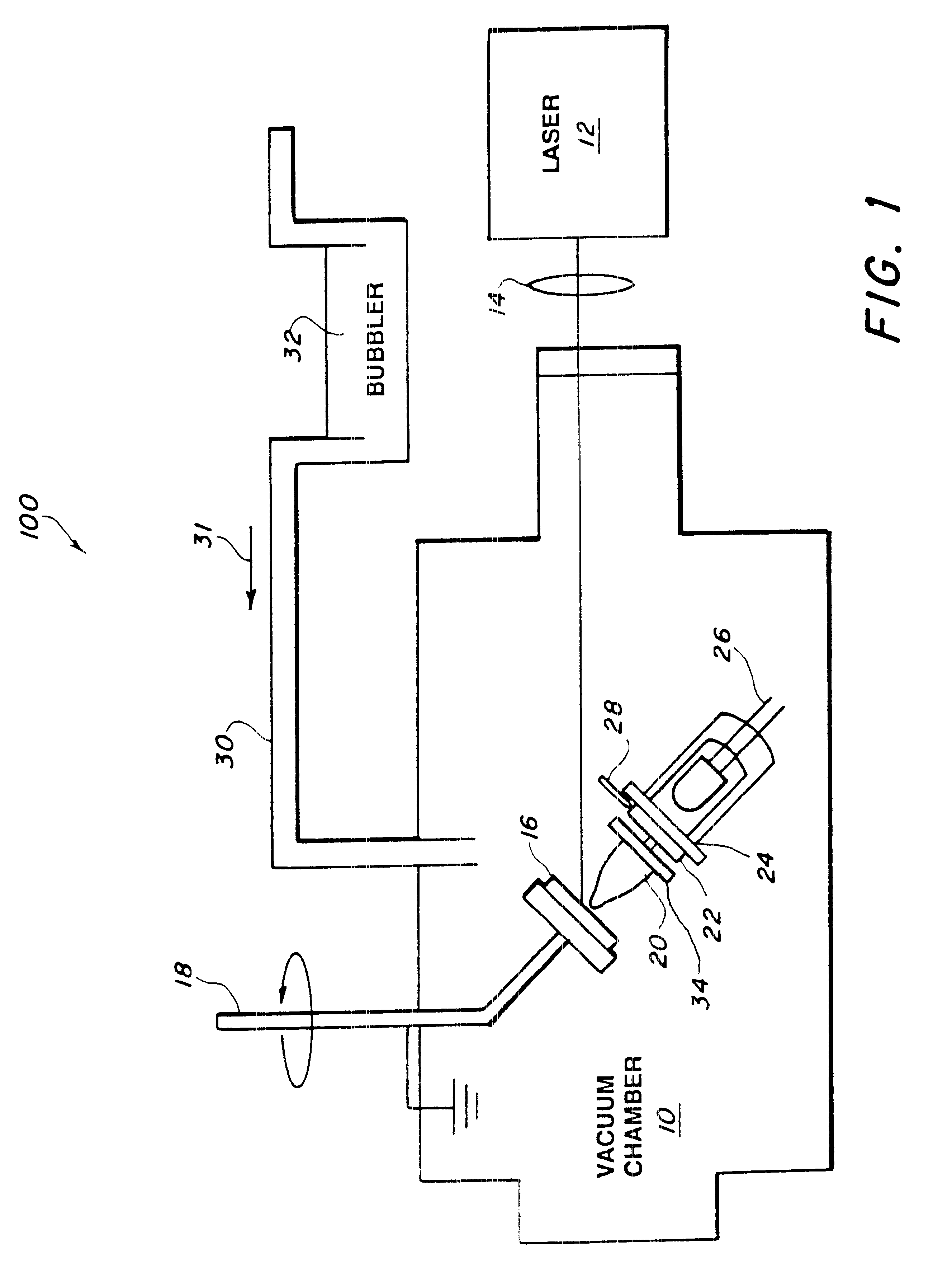
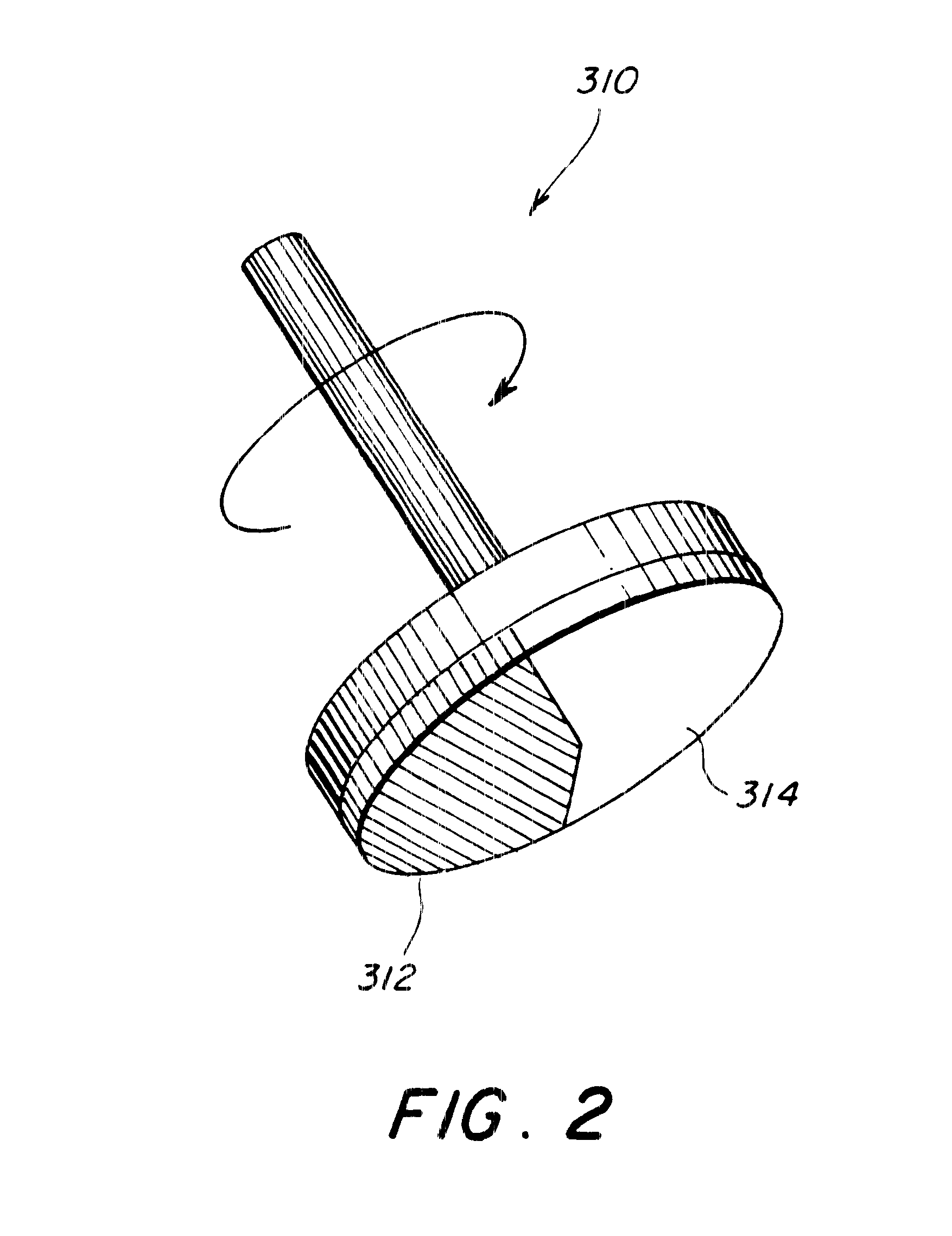
For a polyepichlorohydrin and carbon matrix, a ribbon was prepared by spin coating a film of PECH / graphite on a quartz wafer, at a PECH / graphite thickness of @ 1 .mu.m from a solution in chloroform. The ribbon was exposed to a pulsed laser that transferred the PECH / graphite matrix to a variety of substrates including glass, ceramics (e.g., alumina), plastics (e.g., polyimide), circuit board composites, silicon and metal surfaces. For demonstration purposes, a 500 nm.times.400 .mu.m.times.250 .mu.m bridge was fabricated over and between two gold electrodes. The gold electrodes had previously been deposited on a printed circuit board. Several test structures were prepared at different resistances. In general, on exposure to an uncalibrated acetone vapor source, the chemiresistors ohmic resistance increased by between 5 and 10% of the initial value 100 K ohm, and in less than 1 second. After removal of the acetone, the resistances returned to their original values in approximately the ...


PUM

PropertyMeasurementUnit
sizeaaaaaaaaaa
distanceaaaaaaaaaa
pressureaaaaaaaaaa

Abstract

A composite layer of a sorbent, chemoselective, non-electrically-conducting polymer and nano-particles of an electrically conducting material dispersed throughout the polymer is formed on a substrate by pulsed laser deposition, matrix assisted pulsed laser evaporation or matrix assisted pulsed laser evaporation direct writing.

Description

1. Field of the InventionThe invention relates generally to the deposition of materials and more specifically to the creation by laser deposition of composite layers of non-electrically-conducting polymers and electrically conducting particles.2. Description of the Related ArtA chemiresistor is a chemical sensor made of a material that has an electrical resistance that varies in response to the presence or absence of an analyte. Typically, a chemiresistor comprises a composite coating of a non-conducting material (such as a chemoselective polymer) and a conducting material (such as carbon or metallic nanoparticles). The conducting material is dispersed throughout the non-conducting material with a sufficient density so that in the absence of an analyte, the chemiresistor conducts electricity. When the chemiresistor is exposed to an analyte, the analyte is absorbed by the non-conducting material, causing the composite coating to swell and causing the conducting particles to move fart...

Claims


Application Information

Patent Timeline
Patent Type & Authority Patents(United States)
IPC IPC(8): B05D7/24C23C14/28C23C14/06C23C14/12
CPCB05D1/60B82Y30/00C23C14/28C23C14/12C23C14/06
Inventor MCGILL, R. ANDREWCHRISEY, DOUGLAS B.PIQUE, ALBERTO
Owner THE GOVERNMENT OF THE UNITED STATES OF AMERICA AS REPRESENTED BY THE SEC OF THE NAVY NAVAL RES LAB WASHINGTON
Why Eureka
Try Eureka