Electronic apparatus and electronic apparatus information display method

a technology of electronic apparatus and information display method, which is applied in the field of electronic apparatus, can solve the problems of not always showing information in the vicinity, difficult to mark all of these beforehand on the top surface of the keys, and small light emitting devices used for electrical status displays

Inactive Publication Date: 2003-12-09
LENOVO (SINGAPORE) PTE LTD
View PDF11 Cites 10 Cited by
  • Summary
  • Abstract
  • Description
  • Claims
  • Application Information

AI Technical Summary

Problems solved by technology

However, light emitting devices used for electrical status displays heretofore have been small and difficult for the user to see.
Also, function keys can be assigned a variety of functions by various applications, and it is difficult to mark all of these beforehand on the top surfaces of the keys.
However, such information is not always displayed in the vicinity of a member, such as a key or push button, to be operated.
It would be difficult for a user to quickly access the member in response to the displayed information.
As a result of having all characters that can be input in a plurality of modes marked on the top surfaces of character input keys on a conventional computer keyboard, it is difficult for the user to identify the character to be input by current operation of a character input key.
Also, since function keys are not marked with the function that can be processed by current operation, these keys are difficult to use.
Also, electrophoretic displays have a memorizing capability and have the advantage of enabling display to be continued simply by applying a voltage pulse only when switching, but on the other hand, have a disadvantage in that the characters of the character input mode prior to switching do not disappear.

Method used


Image

  • Electronic apparatus and electronic apparatus information display method
  • Electronic apparatus and electronic apparatus information display method
  • Electronic apparatus and electronic apparatus information display method

Examples


Embodiment Construction

The present invention will now be described in detail based on the embodiments shown in the attached drawings.

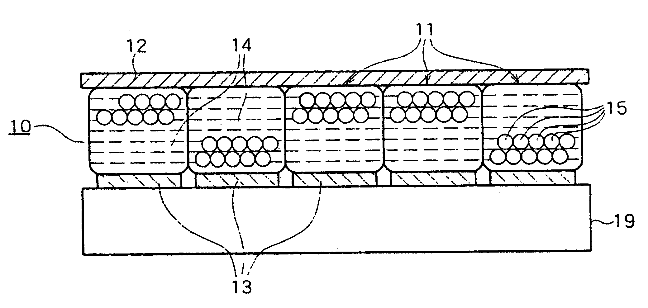
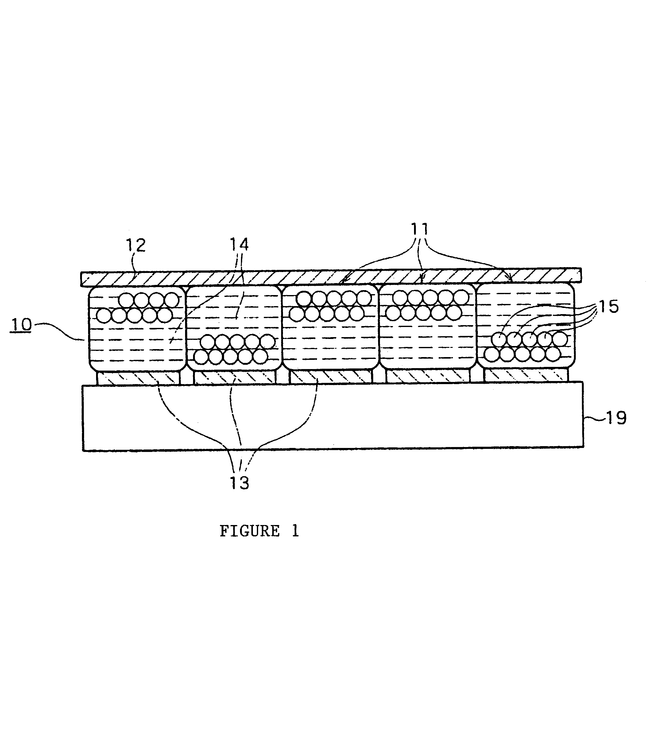
Referring to FIG. 1 there is shown a vertical cross-sectional drawing showing the schematic configuration of an electrophoretic display 10. The electrophoretic display 10 has three layers, cells 11 in the middle looking vertically, and an upper electrode 12 and lower electrodes 13 film, formed on the top and bottom of the cells 11, respectively, and is mounted on the surface of a housing 19. The cells 11 are arranged in one layer vertically and are closely arranged horizontally without gaps between them, and each cell 11 is injected with a colored dispersion medium 14 and a predetermined quantity of white titanium oxide powder 15. The upper electrode 12 is colorless and transparent, and the upper electrode 12 and lower electrodes 13 are arranged in the form of a lattice in a plan view, with each lattice point forming a pixel of the electrophoretic display 10, and with a volt...


PUM


Abstract

An electrophoretic display is mounted on the surface of the housing of a notebook type personal computer. When an event that requires the user to operate a member occurs, the member and operation information corresponding to that event are searched for, and the searched-for operation information is displayed in a region of the electrophoretic display in the vicinity of the searched-for member. For example, when a termination switch is in a corner of the exterior surface of the cover, for a system termination event, information indicating that the termination switch should be operated is displayed in a region of the electrophoretic display in the vicinity of the termination switch.

Description

1. Field of the InventionThe present invention relates to an electronic apparatus, such as a notebook type personal computer, for example, and an electronic apparatus information display method, and relates in particular to an electronic apparatus and electronic apparatus information display method that provides improved information display for the user.2. Description of Related ArtThe use of electrophoretic displays as displays for electronic apparatuses such as electronic books and cards, and the like, is widely known (examples: Japanese National Publication of International Patent Application No. 1999-502950 specification and Published Unexamined Japanese Patent Application No. 2000-285219 specification). Also, in a notebook type personal computer such as an electronic apparatus, the use of an electrophoretic display instead of a liquid crystal display is also widely known (Published Unexamined Japanese Patent Application No. 2000-137250 specification).The advantages of an electr...

Claims


Application Information

Patent Timeline
Patent Type & Authority Patents(United States)
IPC IPC(8): G06F1/16G06F3/023G06F3/02G06F3/048G06F3/0489G09G3/20G09G3/34
CPCG06F1/1616G06F1/1637G06F3/0238G06F1/169G06F1/1649
Inventor TSUJIMURA, TAKATOSHIMIWA, KOICHISUZUKI
Owner LENOVO (SINGAPORE) PTE LTD
Why Eureka
Try Eureka