Wheel steering apparatus

a technology of steering apparatus and wheel, which is applied in the direction of couplings, interlocking clutches, gearing, etc., can solve the problems of considerable loss and adverse effects on the steering ability of the vehicl

Inactive Publication Date: 2003-12-16
NTN CORP
View PDF7 Cites 12 Cited by
  • Summary
  • Abstract
  • Description
  • Claims
  • Application Information

AI Technical Summary

Benefits of technology

According to the present invention, since the rotation of the drive motor is transmitted to the steering rod through the ball screw mechanism, the working efficiency is high with a minimized loss and the drive motor of a compact size is sufficient. While the ball screw mechanism can exhibit a high efficiency even during a reverse drive operation, the provision of the reverse input limiting means is effective to prevent the rotor of the drive motor from being rotated by the effect of an external force which would act on the wheel steering apparatus when, for example, the vehicle then running is hit by crosswind. Accordingly, even though the wheel is affected by the axially acting external force, no external disturbance torque is transmitted to the rotor of the drive motor, thereby to exhibit a stabilized vehicle steerability.
Thus, since no external force is transmitted from the vehicle wheels to the motor rotor, a motor control system can be advantageously simplified. Also, even when the wheel steering apparatus is affected by the external force transmitted from the vehicle wheels, no retaining torque for the drive motor is necessary and, hence, the power consumption by the drive motor can be reduced. Where the vehicle wheels are steered by the utilization of the output from the drive motor, the use of the ball screw mechanism enables it to be rotated lightly and, accordingly, the drive motor can have a reduced capacity.
Integration of the component parts of the clutch assembly with the nut member of the ball screw mechanism makes it possible to achieve a structure compact in size in an axial direction with no necessity to connect the clutch assembly and the nut member together during the assemblage, resulting in reduction in the number of the assembling steps. Also, possible generation of rattling motion of the nut member of the ball screw mechanism which would result from a poor precision of connection between the component parts of the clutch assembly and the nut member of the ball screw mechanism can be relieved, thereby stabilizing the working torque.
According to this design, in the event that while the engagement elements are held at the engaged operative position of the cam faces the output side ring is tended to rotate, rotation in one direction is locked by engagement of the rollers at the cam face portions in such one direction while rotation in the other direction is locked by the cam face portions in such other direction. Accordingly, rotation in these two directions counter to each other is interrupted. On the other hand, in the event of rotation of the input side ring, regardless of whether it rotate in any of the opposite directions, the retainer causes the engagement elements towards the non-engaged position to thereby release the lock with the connecting means consequently held in position to connect with the output side ring to thereby transmit the rotation and, accordingly, transmission of the rotation to the output side ring is possible. In this way, even though the wheel is affected by an external force in any direction, no disturbance torque is transmitted to the rotor of the drive motor and, accordingly it can have a stabilized vehicle steerability.

Problems solved by technology

While the trapezoidal threads can convert a rotational torque of the nut member caused by the drive motor into an axial thrust force (a positive thrust operation), the positive operating efficiency of the trapezoidal threads is generally 50% or lower and, therefore, a loss is considerably large.
However, if the ball screw mechanism is used in the rear wheel steering apparatus, since the efficiency is high during a reverse operation, the steerability of the vehicle appears to be adversely affected as a result of increase of the torque generated in a rotor of the drive motor, when the rear wheel steering apparatus is affected by an external force which would act on the wheel steering apparatus when, for example, the vehicle then running is hit by crosswind.

Method used


Image

  • Wheel steering apparatus
  • Wheel steering apparatus
  • Wheel steering apparatus

Examples


second embodiment

The second embodiment shown in and described with reference to FIGS. 7 to 9 may be regarded as more specific than the previously described first embodiment and, except for those described with reference to FIGS. 7 to 9, the details thereof are substantially identical with those in the previously described first embodiment.

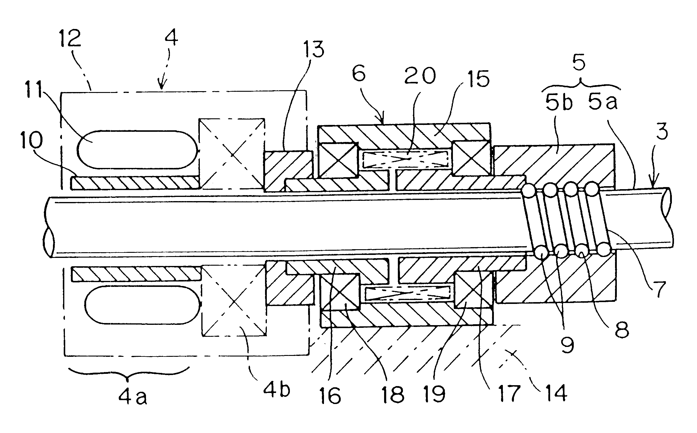
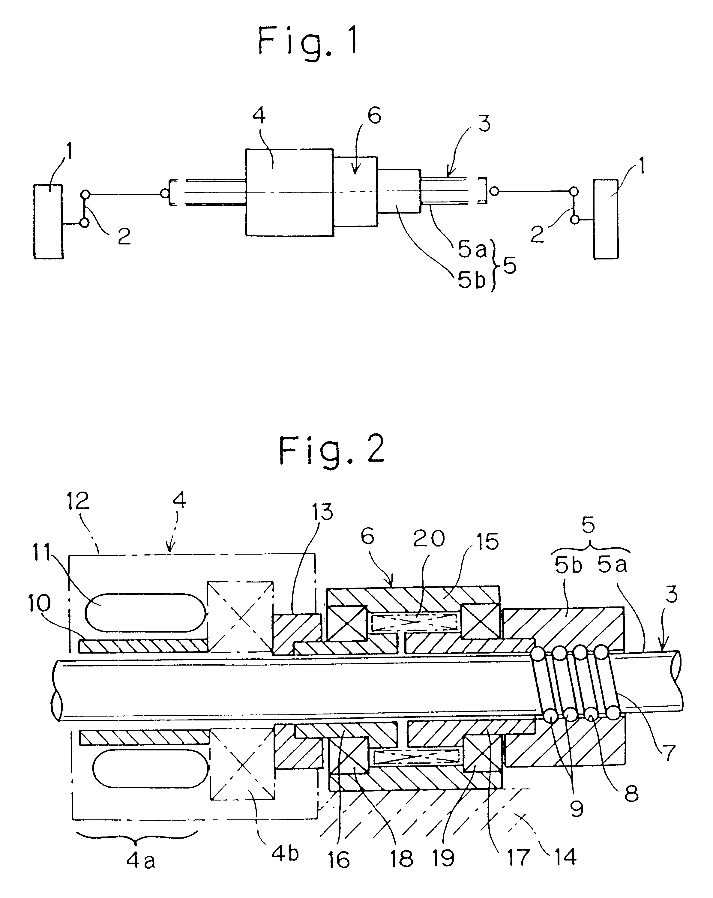
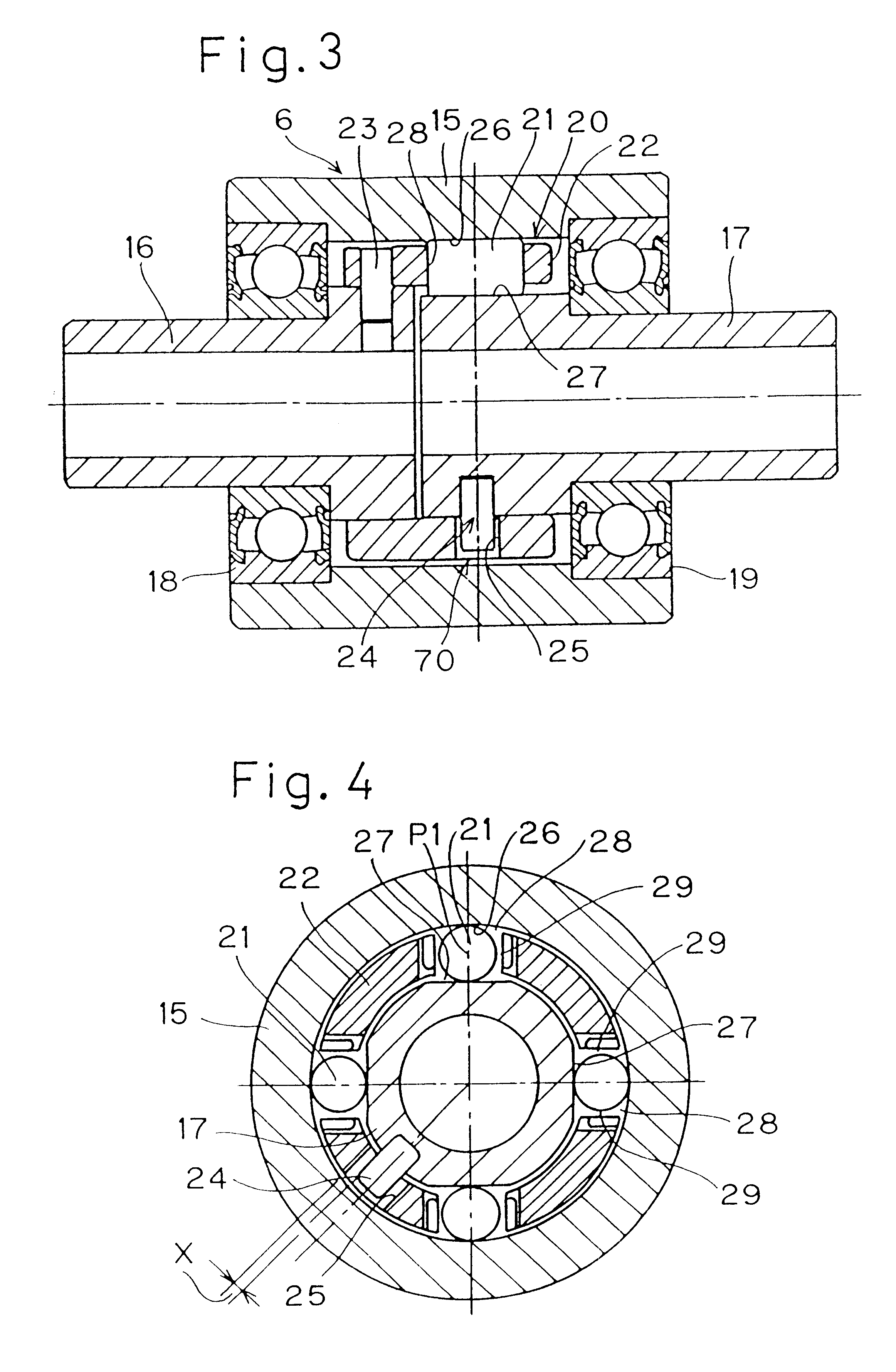
A third preferred embodiment of the present invention is shown in FIGS. 10 to 13. The wheel steering apparatus according to this embodiment is substantially similar to that according to the first embodiment shown in and described with reference to FIGS. 1 to 6, except for the following structural features. It is, however, to be noted that even in this embodiment shown in FIGS. 10 to 13, the clutch assembly 6, now identified by 6C, is a two-way clutch assembly of a reverse input limiting type that is, as regards the rotations in opposite directions are concerned, operable to transmit rotation from an input side ring 16C to an output side ring 17C, but to interrupt t...


PUM


Abstract

To provide a wheel steering apparatus capable of exhibiting a stabilized vehicle steerability without transmitting an external disturbance torque to a motor rotor even when the wheel receives an axially acting external force, this wheel steering apparatus includes a reciprocatingly movable rod 3 drivingly connected with a support member 2 for steerably supporting a wheel 1, and a ball screw mechanism 5 for reciprocatingly moving the rod 3 in response to rotation of a drive motor 4. In a rotational transmission system for transmitting rotation of the drive motor 4 to a nut member 5b of the ball screw mechanism 5, a clutch assembly 6 defining a reverse input limiting means is provided for preventing a rotar of the drive motor 4 from being rotated by the external force acting on the wheel 1. This clutch assembly 6 used is of a design wherein although rotation can be transmitted from an input shaft to an output shaft, no rotation is transmitted from the output shaft to the input shaft.

Description

1. Field of the InventionThe present invention relates to a wheel steering apparatus for use in association with an active rear steering (ARS) system of an automotive vehicle or the like.2. Description of the Prior ArtAn automotive vehicle having its front wheels adapted to be steered through a steering wheel has recently come to employ an active rear steering (ARS) system. The ARS system is an electronic control system for monitoring the wheel speed of the front wheel pair of the automotive vehicle and for controlling the steering of the rear wheel angle so that the vehicle body can attain a target body slip angle. A wheel steering apparatus for the rear wheel pair that can be used in association with this system is generally so configured that a reciprocatingly movable rod drivingly connected with support members for the rear wheels can be reciprocatingly moved by an electronically controlled drive motor through a screw mechanism used to translate a rotary motion of the drive moto...

Claims


Application Information

Patent Timeline
Patent Type & Authority Patents(United States)
IPC IPC(8): F16D41/00F16D41/067F16H25/20F16D41/06B62D5/04
CPCF16D41/067F16H25/20Y10T74/18576Y10T74/18696F16H25/2204
Inventor YOSHIDA, ISAMUKAZUNO, KEISUKESATO
Owner NTN CORP
Why Eureka
Try Eureka