
Electric treatment system

a treatment system and treatment method technology, applied in the field of electric treatment system, can solve the problems of time-consuming and laborious work, increased complexity of techniques and devices, and troublesome users, and achieve the effect of reducing the work involved in changing connections and settings

Inactive Publication Date: 2003-12-23
OLYMPUS CORP
View PDF18 Cites 934 Cited by
  • Summary
  • Abstract
  • Description
  • Claims
  • Application Information

AI Technical Summary

Benefits of technology

It is an object of the present invention to provide an electric treatment system that is capable of reducing work involved in changing connections and settings by controlling the operation of a medical instrument corresponding to a hand piece connected to the medical instrument, even when a different of types of hand pieces can be connected to a different of types of medical instruments.
It is another object of the present invention to provide an electric treatment system that is capable of smoothly performing a treatment and offering a good operability.

Problems solved by technology

However, with recent advances in technologies and increasing complexity of techniques and devices, even when a hand piece is merely used, a plurality of devices must be controlled simultaneously, rather than a single device.
In this event, the electric knife is not used under an endoscope, therefor the operation of the pneumoperitoneum apparatus associated with the output may cause some trouble.
In an operation field, such apparatus are typically concentrated on a single carrier or the like for connection, therefor a change in connection, if required each time the electric knife is not used under the endoscope, is troublesome for the user.
The time-consuming and laborious work improve upon to the user does constitute a problem as is the case in the aforementioned Japanese Patent Laid-Open No.

Method used


Image

  • Electric treatment system
  • Electric treatment system
  • Electric treatment system

Examples


first embodiment

The first embodiment has the following advantages.

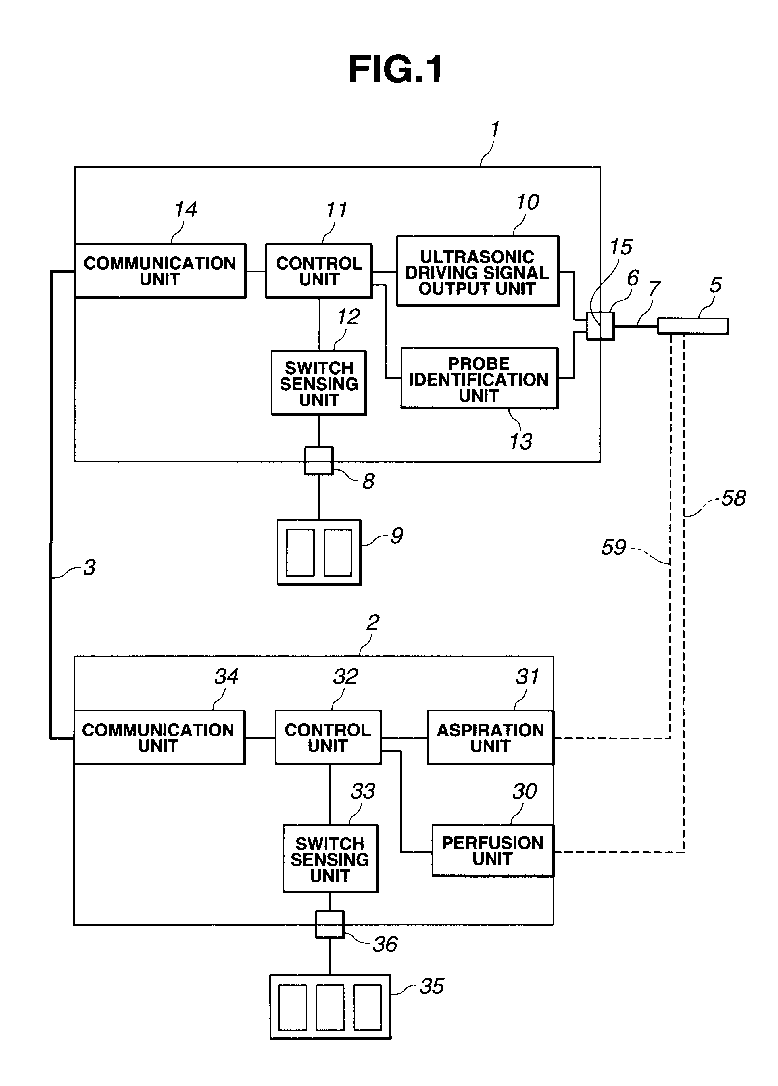
According to the first embodiment as described above, since the type of a hand piece (probe) connected to the ultrasonic wave output apparatus is identified to determine whether or not the associative control of the ultrasonic wave output apparatus with the perfusion / aspiration apparatus is required in accordance with the identified type of the hand piece, unintended perfusion and aspiration functions will not operate when ultrasonic waves are output. Also, this eliminates time-consuming and laborious works for re-connection of the ultrasonic wave output apparatus and the perfusion / aspiration apparatus in accordance with the type of a particular probe, so that the operability can be improved during an ultrasonic operation.

Also, by selectively performing the associative control in accordance with a connected hand piece, if the ultrasonic wave output apparatus and / or the perfusion / aspiration apparatus fail, the hand piece for use only ...

second embodiment

The second embodiment has the following advantages.

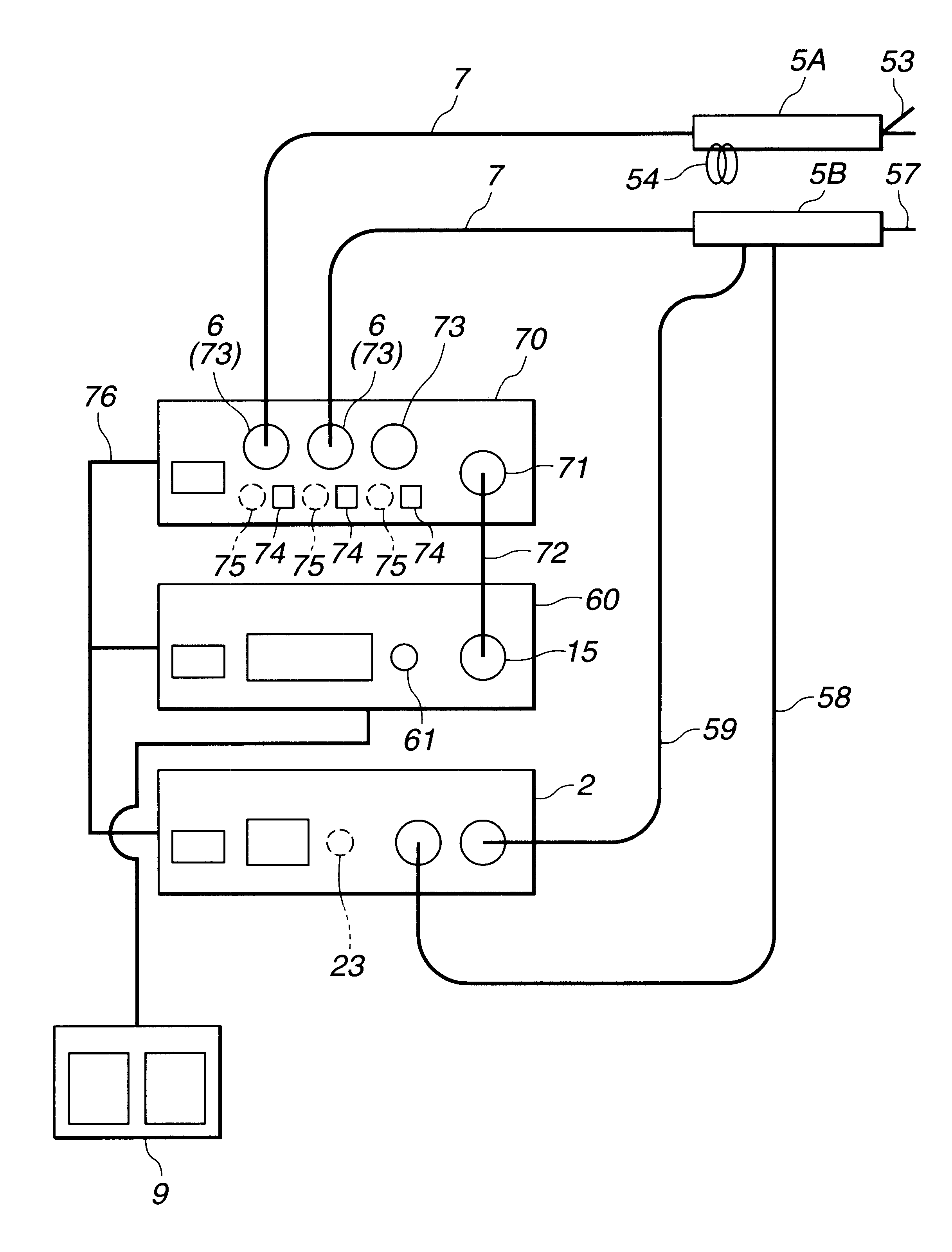
According to the second embodiment as described above, when a plurality of ultrasonic aspiration hand pieces 5B are used, the re-connection of the cable 7 the re-connection of the perfusion tube 58 and the inconnections of the aspiration tube 59 are eliminated, thereby making it possible to further improve the operability, in addition to the advantages provided in the respective embodiments described above.

third embodiment

(Third Embodiment)

Next, a third embodiment of the present invention will be described with reference to FIGS. 7 through 9.

An ultrasonic operation system 101 illustrated in FIG. 7 comprises an ultrasonic wave output apparatus 102 for outputting an ultrasonic driving signal and for controlling the output; a perfusion / aspiration apparatus 103 connected to the ultrasonic wave output apparatus 102 through a communication cable 108 for performing perfusion and aspiration; an ultrasonic aspiration probe 104 removably connected to the ultrasonic wave output apparatus 102 and to the perfusion / aspiration apparatus 103, for example, as an ultrasonic treatment tool is grabbed by the operator for performing an ultrasonic treatment, for performing an ultrasonic-based aspiration treatment; an ultrasonic coagulation / incision probe 105 removably connected to the ultrasonic wave output apparatus 102 for performing ultrasonic-based coagulation and incision treatments; a twin foot switch 106 connected ...


PUM


Abstract

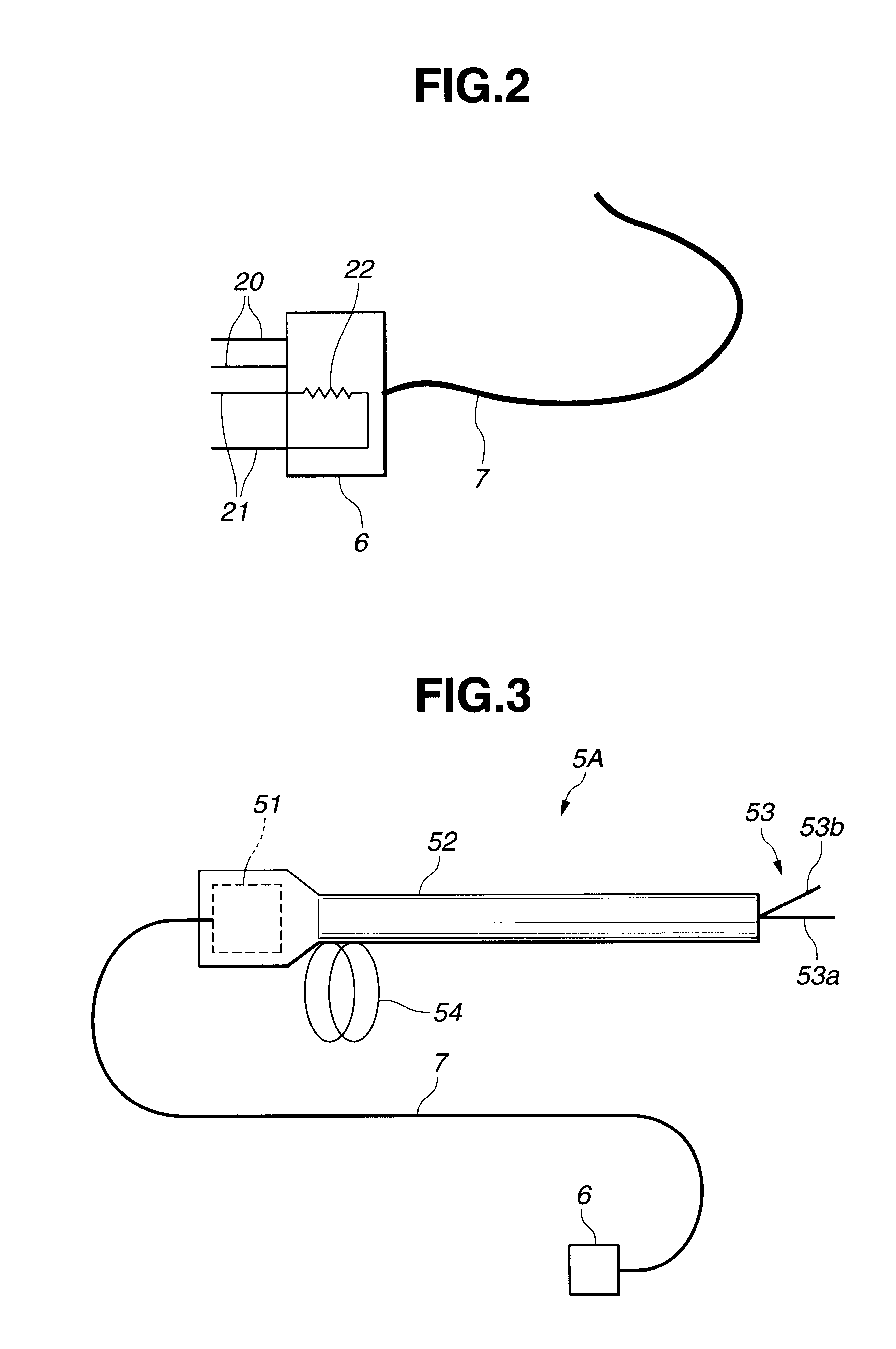
A treatment tool for performing a treatment for a curative procedure with ultrasonic waves, high frequency current and so on is provided with an identifier formed of a resistor or the like for indicating the type of the treatment tool. A medical instrument such as an ultrasonic wave output apparatus discriminates the type of a treatment tool connected thereto from the identifier to automatically set operating parameters such as an output value suitable for the treatment tool and to associatively operate an ancillary medical instrument such as a perfusion / aspiration apparatus depending on the treatment tool, thereby reducing extra work such as manual setting to allow for a smooth treatment.

Description

This application claims benefit of Japanese Application Nos. Hei 11-237551 filed in Japan on Aug. 24, 1999, Hei 11-294331 filed in Japan on Oct. 15, 1999, Hei 11-294332 filed in Japan on Oct. 15, 1999, Hei 11-304283 filed in Japan on Oct. 26, 1999, 2000-197252 filed in Japan on Jun. 29, 2000, the contents of which are hereby incorporated by reference.Field of the Invention and Description of the Related ArtThe present invention relates to an electric treatment system for electrically performing a treatment for a curative procedure.In recent years, electric treatment apparatus have been widely used. Examples of such are electric knives, which conduct a high frequency current to perform a treatment in a curative procedure, and ultrasonic treatment apparatus which utilize ultrasonic waves to perform a treatment an the curative procedure.For example, an ultrasonic treatment apparatus disclosed in Japanese Patent No. 2578250 is composed of a hand piece, a probe, an ultrasonic wave output...

Claims


Application Information

Patent Timeline
Patent Type & Authority Patents(United States)
IPC IPC(8): A61B17/32A61B18/12A61B18/14A61M1/00A61B17/00
CPCA61B17/320068A61B18/12A61B18/14A61B2217/007A61B2017/00482A61B2217/005A61B2017/00199A61B2017/320069A61B2017/32007A61B2017/320082
Inventor TAKAHASHI, HIROYUKI
Owner OLYMPUS CORP
Learn More