Concrete stone texturing machine, method and product

a texturing machine and concrete technology, applied in the direction of grinding drives, manufacturing tools, working accessories, etc., can solve the problems of very physical operation, only superficial roughening or abraded process, cost and hazardous operation

Inactive Publication Date: 2003-12-30
CICCARELLO CHARLES
View PDF16 Cites 47 Cited by
  • Summary
  • Abstract
  • Description
  • Claims
  • Application Information

AI Technical Summary

Benefits of technology

It is a feature of the present invention to provide a concrete stone facing machine which substantially overcomes the disadvantages of the prior art and meets the needs for production of concrete stones having a projecting irregular front rough surface to resemble a real stone face.

Problems solved by technology

This machine is not for chipping a stone to form an irregular rough surface to resemble a real stone face.
This has been a costly and hazardous operation as a percentage of the tumble stones will fragment and then have to be discarded.
They are also labour intensive, result in injuries and the operation is very physical requiring shift work of short duration.
However, this roughened or abraded process is only superficial on the surfaces and edges of the block and do not deeply penetrate the surfaces.
Real stone faces have a deeper and irregular texture which these machines and process cannot achieve.

Method used


Image

  • Concrete stone texturing machine, method and product
  • Concrete stone texturing machine, method and product
  • Concrete stone texturing machine, method and product

Examples


Embodiment Construction

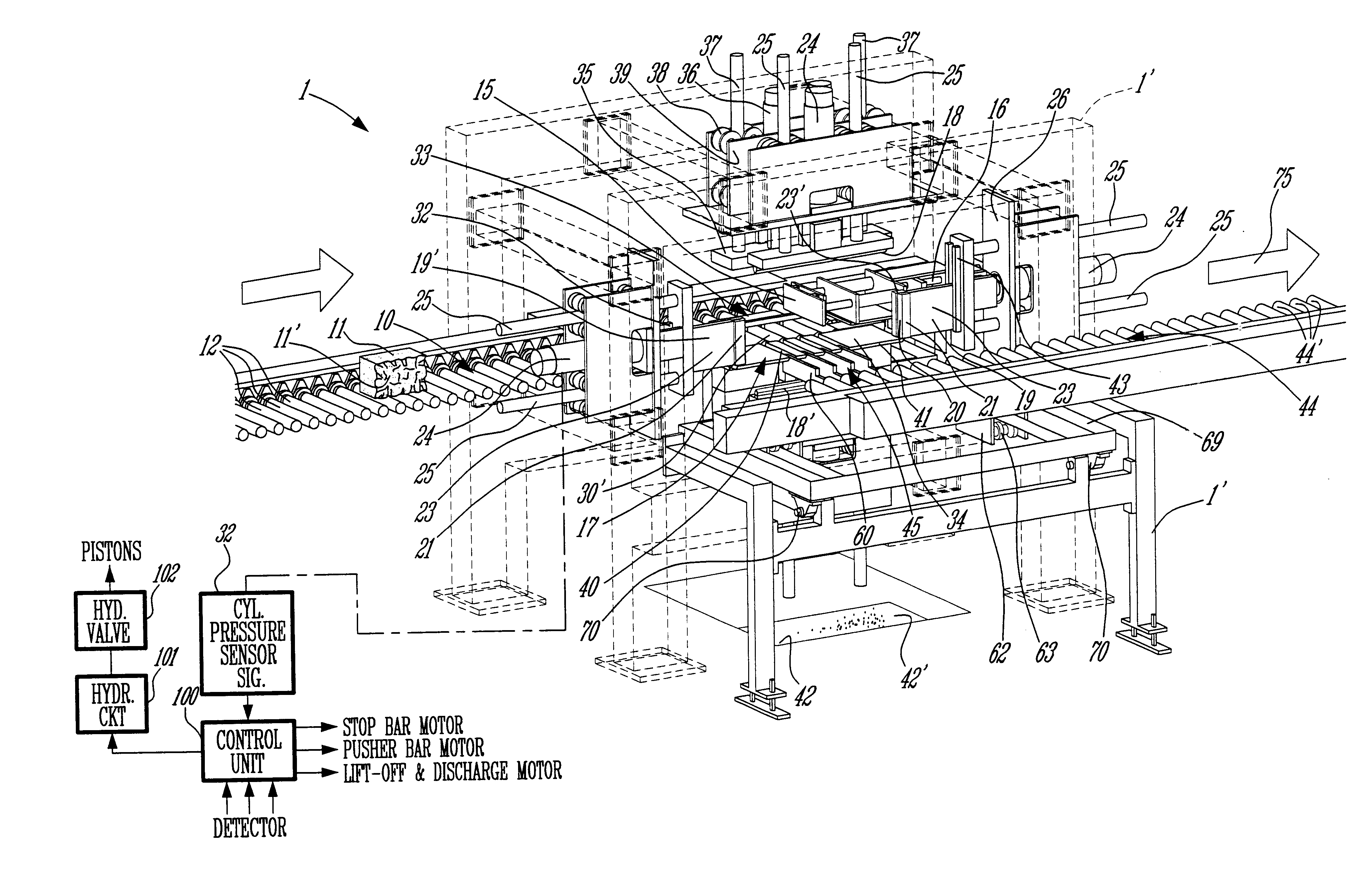
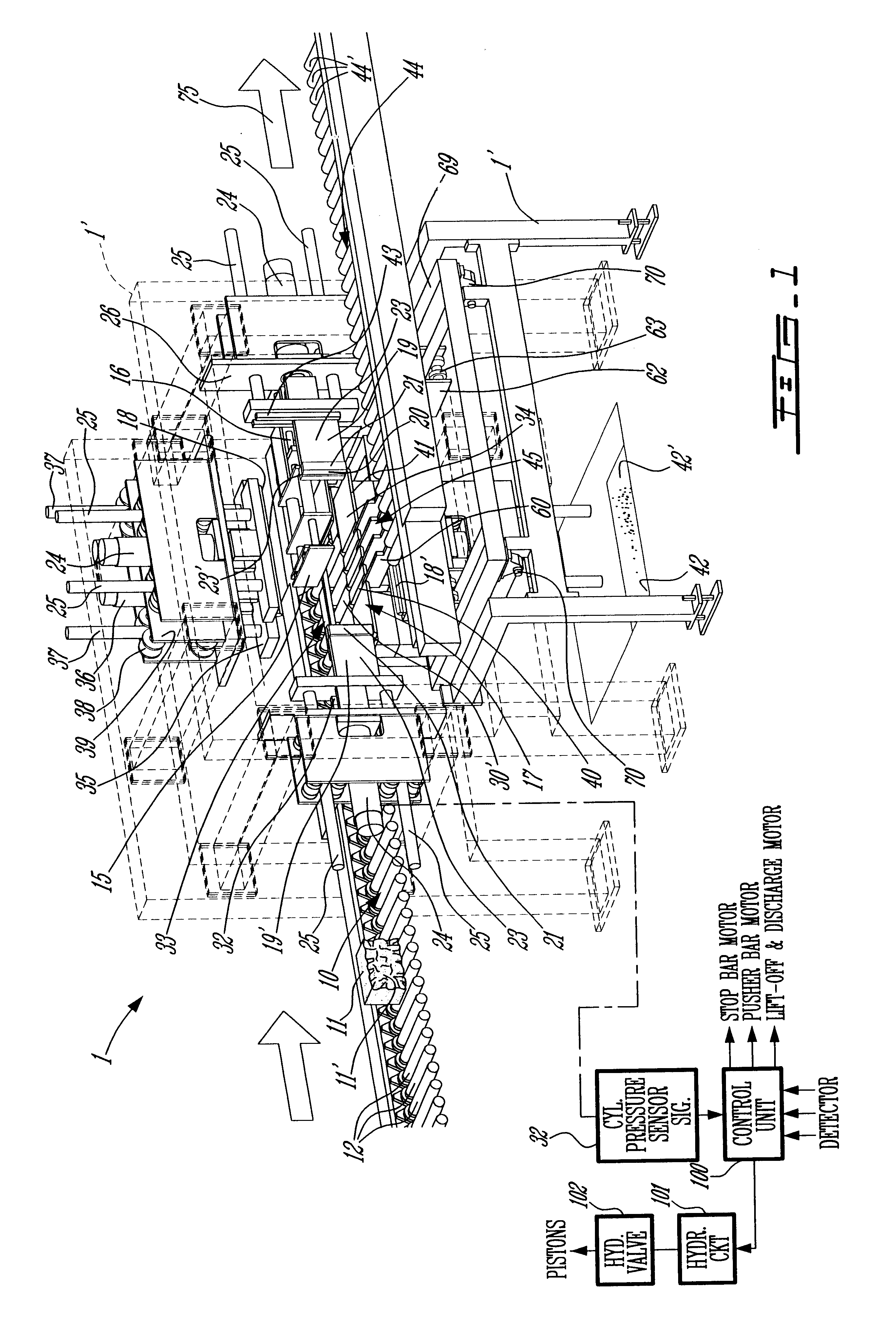
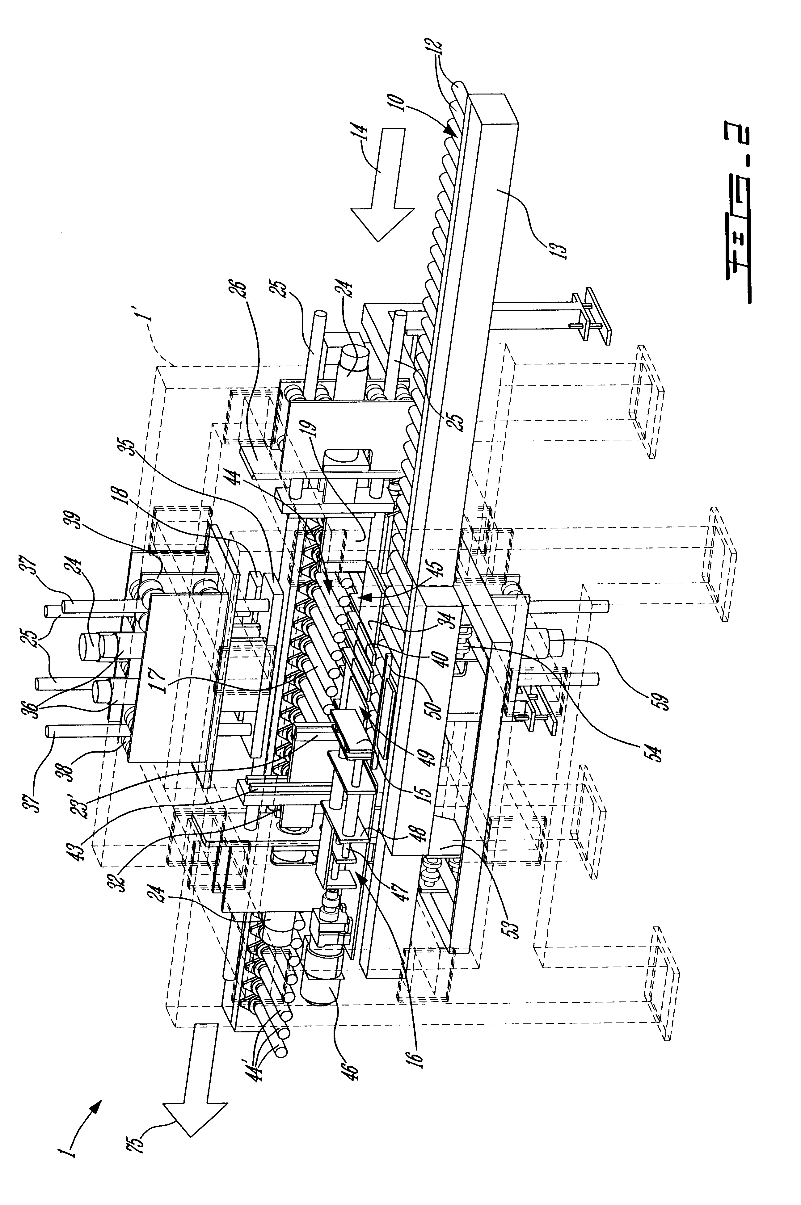
Referring now to the drawings, and more particularly to FIGS. 1 to 4, there is illustrated a concrete stone facing machine 1 constructed in accordance with the present invention whereby to fabricate the concrete stone 2, as illustrated in FIG. 11, which is formed with opposed surrounding flat walls 3 and 3' and having a projecting irregular rough front surface 4 which resembles a real stone face. As shown in FIG. 11, the stones produced by the machine 1 of the present invention have in their opposed flat walls, and immediately adjacent the deep rough contour of its front surface 4, two groups of spaced apart blade indentations, namely, group 5 and group 6 of blade indentations and which are aligned along respective straight, parallel axes 5' and 6'. These are also present on the side faces 3'. These blade indentations and their offset are herein shown exaggerated to illustrate that there is a small spacing between them to achieve the texturing of the front face 4 of the concrete sto...


PUM

PropertyMeasurementUnit
distanceaaaaaaaaaa
distanceaaaaaaaaaa
distanceaaaaaaaaaa

Abstract

A concrete stone texturing machine, method and a stone having an irregular rough surface resembling a real stone face is described. The machine conveys concrete stones having opposed flat surfaces to a pitching station having at least one pair of opposed pitching blade assembles aligned in a common plane on a respective side of the pitching station. The pitching blade assemblies are displaced towards and away from one another a predetermined distance. Each assembly has a plurality of pitching blades secured in side-by-side aligned relationship. Each of the pitching blades has a forward projecting cutting edge and a securing body portion. A first group of the pitching blades has their cutting edges aligned along a first straight cutting axis which is offset from the cutting edges of the second group of pitching blades aligned along a second straight cutting axis. The cutting axes are parallel to one another. With the offset cutting edges a unique appearance of the pitched blocks surface is obtained when the pitching blades are forced to penetrate a predetermined distance in an associated one of the surrounding transverse faces of the block adjacent a surface to be pitched.

Description

The present invention relates to a concrete stone facing machine, its method of operation and the resulting concrete stone block having an irregular rough surface which is chipped to resemble a real stone face.There has been a need for several decades to develop a machine capable of facing stones by chipping the stone to form a rough surface resembling a real stone. For example, in U.S. Pat. No. 2,867,204, issued on Jan. 6, 1959, there is proposed a machine which is provided with two opposed chisels which are disposed against opposed surfaces of a stone adjacent a face to be roughened. These chisels are impacted by hammers whereby to simulate a conventional method that a mason uses to chip a stone. U.S. Pat. No. 2,912,969, also issued in 1959, describes a stone dressing and planing machine which utilizes a pair of opposed vertically movable, horizontal blades and a pair of vertical blades operated by rams. These pair of blades are actuated in unison, one after the other whereby to s...

Claims


Application Information

Patent Timeline
Patent Type & Authority Patents(United States)
IPC IPC(8): B28D7/00B28D7/04B28D1/30B28D1/22B28D1/00
CPCB28D1/222B28D7/04B28D1/30
Inventor PEDERSEN, HANSCICCARELLO, CHARLES
Owner CICCARELLO CHARLES
Why Eureka
Try Eureka