Deployable radiator for a space vehicle

a technology for space vehicles and radiators, applied in the field of space vehicles, can solve the problems of compromising the effectiveness of heat radiators, limited energy available for transfer, and inability to provide thermal insulation during the transfer stag

Inactive Publication Date: 2003-12-30
ALCATEL LUCENT SAS
View PDF15 Cites 31 Cited by
  • Summary
  • Abstract
  • Description
  • Claims
  • Application Information

AI Technical Summary

Problems solved by technology

Deployable radiators are used when the fixed areas inherent to the structure of the satellite are not sufficient to dump all of the heat that is generated on board.
In all cases, the energy available for transfer is limited by the energy collection or storage means which must be dimensioned as sparingly as possible.
Thus, in all cases, since the available energy is only just sufficient, it must not be wasted insofar as that is possible during the transfer stage.
In contrast, once the satellite is on-station in the geostationary orbit, their effectiveness as heat radiators is compromised by the fact that approximately half of the available surface area is insulating and not radiating.
The deployable radiators of document D2 are radiating over both faces in full, but they provide no thermal insulation during the transfer stage.

Method used


Image

  • Deployable radiator for a space vehicle
  • Deployable radiator for a space vehicle
  • Deployable radiator for a space vehicle

Examples


Embodiment Construction

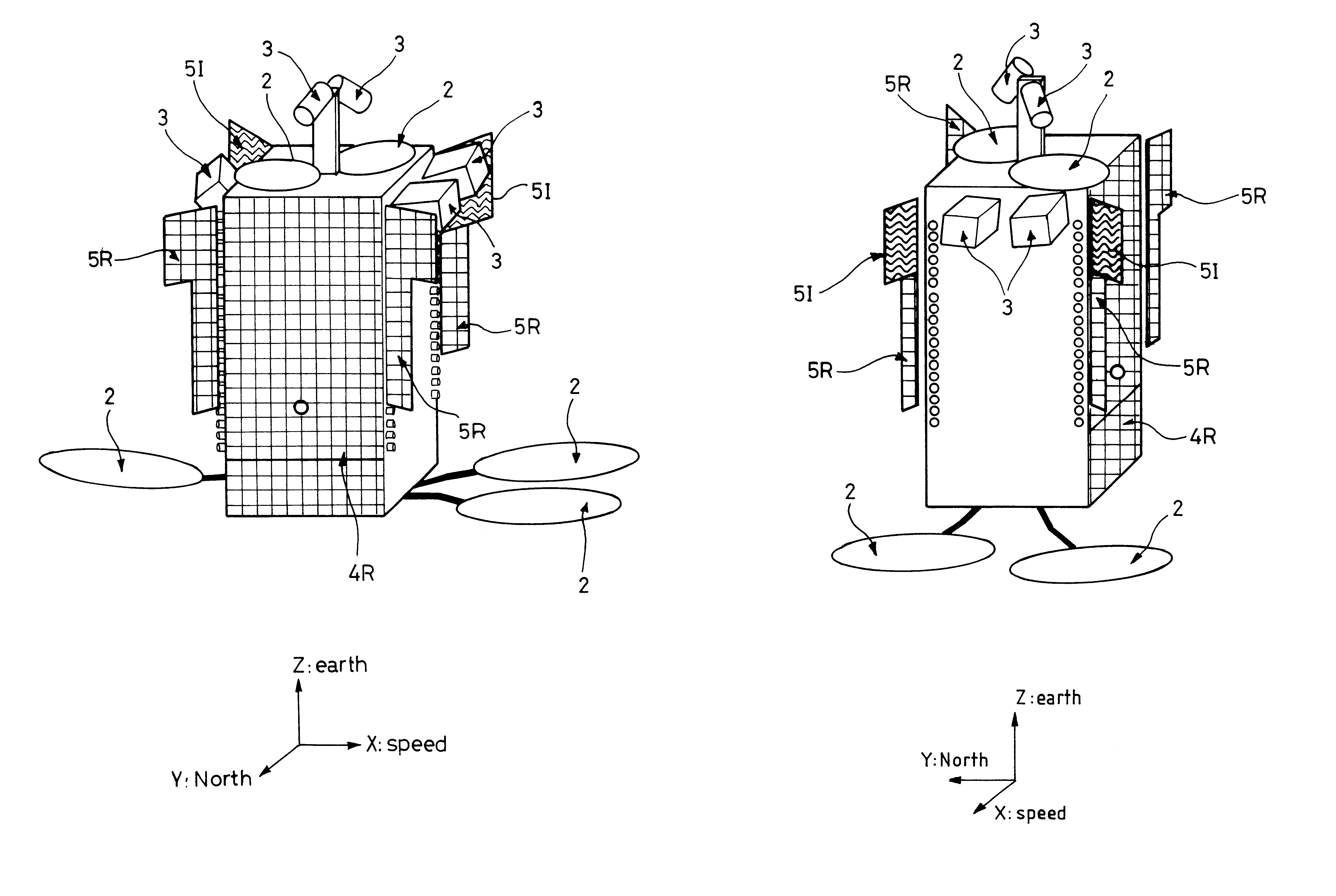
In all the figures, the same references refer to the same elements. The scale is not always the same for reasons of clarity and legibility.

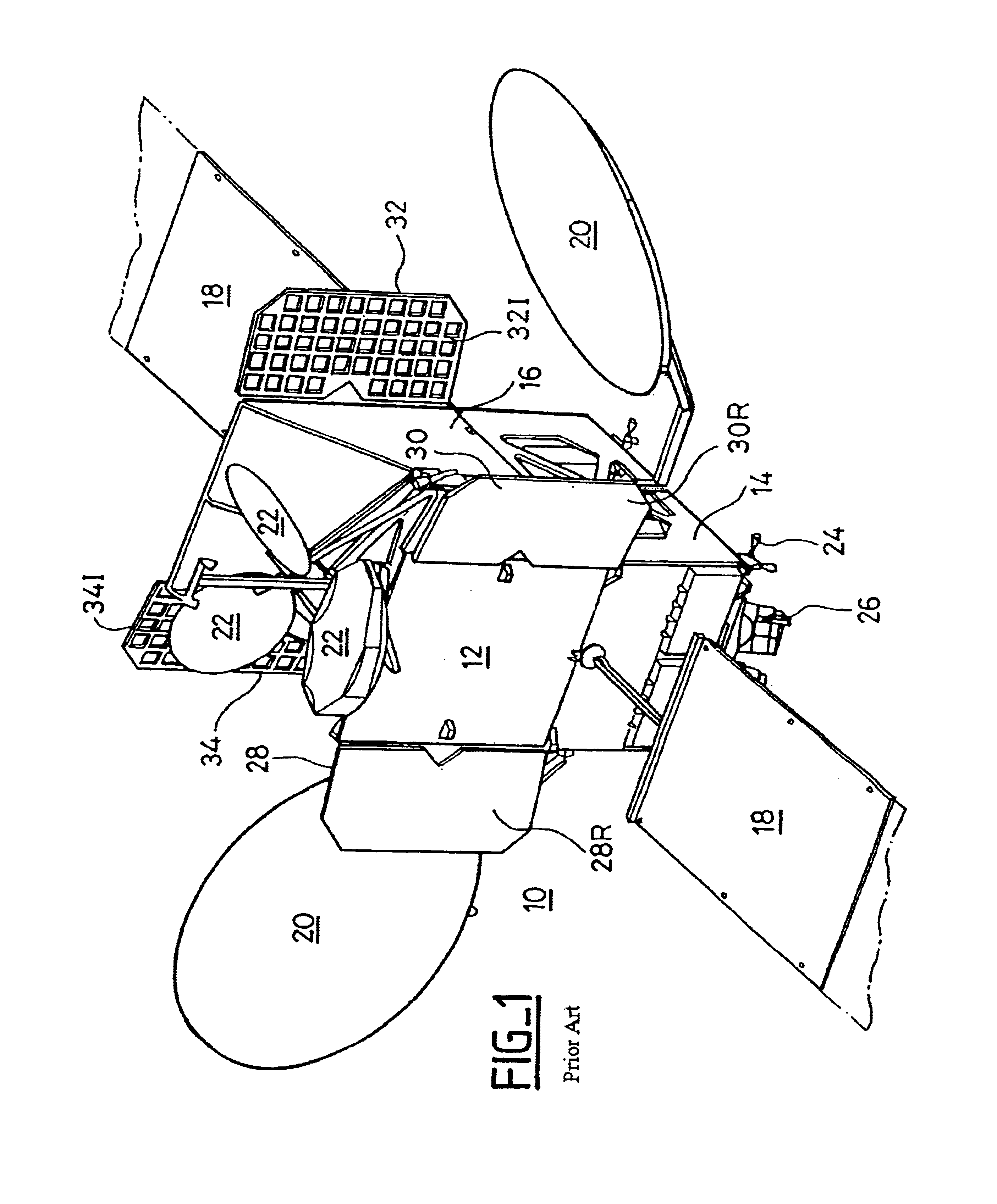
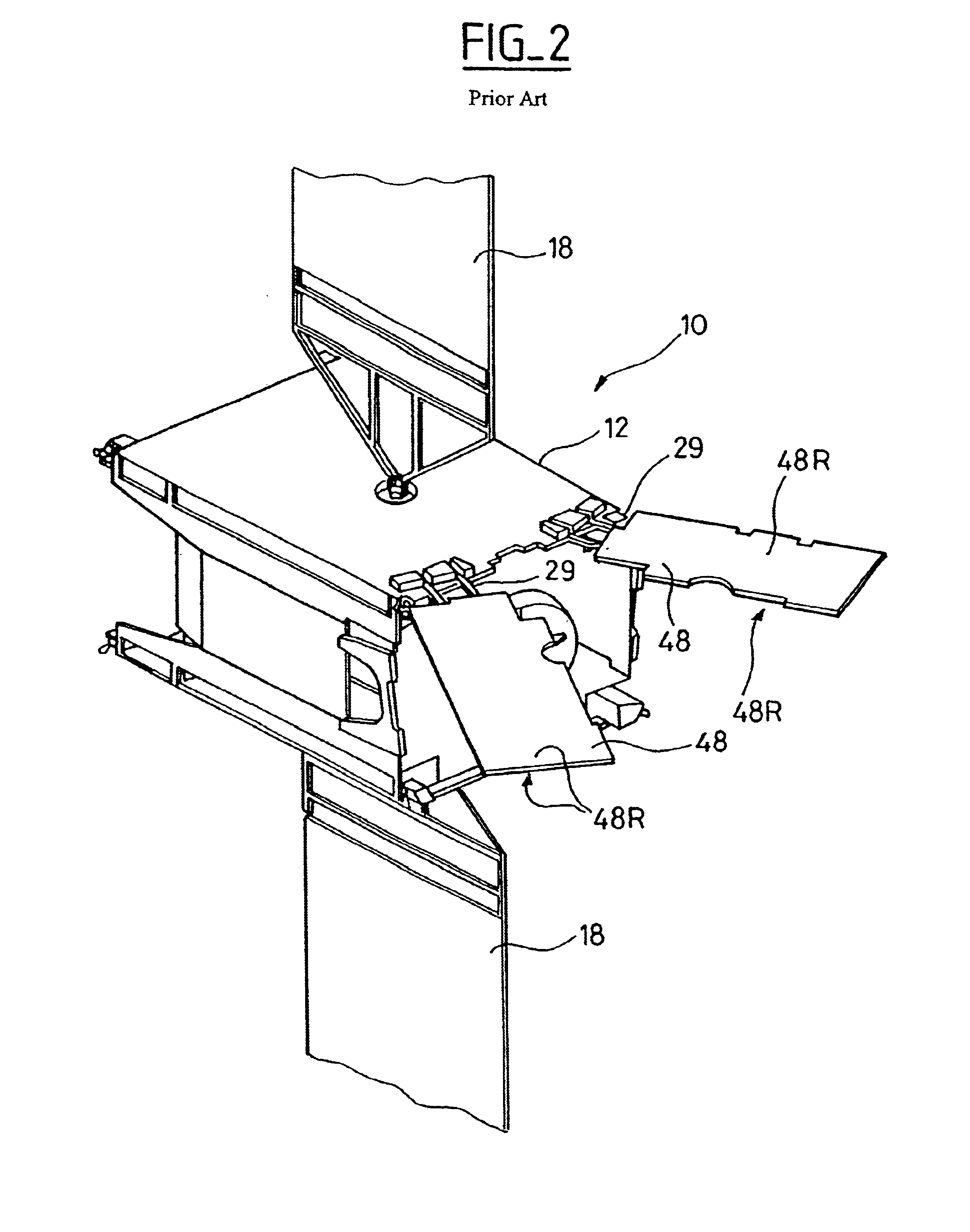
FIG. 1 shows a satellite 10 known in the prior art from document D1. The satellite 10 mainly comprises a service module 14 and a communications module 16. Deployable radiators 28, 30, 32, and 34 are shown in the deployed position.

The heat to be dumped which comes from equipment fixed within the structure 12 of the satellite 10 is conveyed to the radiators by means of heat pipes (not shown) each having a flexible portion corresponding to the hinge(s) for fixing the deployable radiators to the structure 12 of the satellite.

Various pieces of propulsion equipment are provided to maneuver the position of the satellite, both during stages in which the satellite is transferred from one orbit to another, and during the mission of the satellite for the purpose of keeping the satellite on station. In FIG. 1, there can be seen two pairs of chemical propulsi...


PUM


Abstract

The invention provides a deployable radiator for a space vehicle such as a satellite. The radiator of the invention has two radiating faces, one of which is insulating over a portion of its area so that during launch and while the satellite is being moved onto station, with the radiator in the stored position, it naturally serves to keep the highest possible temperature on board the vehicle.

Description

The present invention relates to space vehicles such as satellites and probes carrying electronic or optical payloads. Such vehicles are typically provided with means for generating, storing, and distributing electricity to power all of the on-board electronics. Depending on the electrical efficiency specific to each piece of electronic equipment, the equipment dissipates as heat a fraction of the electrical energy it consumes in operation. This heat must be distributed and channeled by conduction and must then be dumped from the space vehicle into the vacuum of space by radiation. The invention relates to heat radiators for performing this function.Various configurations of fixed or deployable radiators are known that are of dimensions which vary with the size and the electrical power of satellites. A present trend in telecommunications satellites is to have ever increasing dimensions and also to have power generators of ever increasing power, thus giving rise to a need for increas...

Claims


Application Information

Patent Timeline
Patent Type & Authority Patents(United States)
IPC IPC(8): B64G1/46B64G1/50B64G1/22
CPCB64G1/503B64G1/222B64G1/506
Inventor BERTHEUX, PHILIPPETEXIER, EMMANUELJACQUE, BERNARDSEGUIN, JEAN-MARIE
Owner ALCATEL LUCENT SAS
Why Eureka
Try Eureka