Compact manifold trunnion ball valve

a manifold and ball valve technology, applied in the field of ball valves, can solve the problems of destroying the same, excessive wear on the downstream seal, and high operating torque that is undesirabl

Inactive Publication Date: 2003-12-30
ARRAY HLDG
View PDF39 Cites 52 Cited by
  • Summary
  • Abstract
  • Description
  • Claims
  • Application Information

AI Technical Summary

Problems solved by technology

Compact manifold ball valves currently manufactured and used in manifold testing systems utilize floating balls and when in the closed position, produce excessive loads on the downstream seats, therefore creating high operating torques that are undesirable.
These increased torques also cause excessive wear on the downstream seal and eventually destroy the same.
In addition, gear operators or other types of actuators with high output torques are commonly required to operate this type of manifold valve, resulting in additional costs.
Another problem that is frequently present ...

Method used


Image

  • Compact manifold trunnion ball valve
  • Compact manifold trunnion ball valve
  • Compact manifold trunnion ball valve

Examples


Embodiment Construction

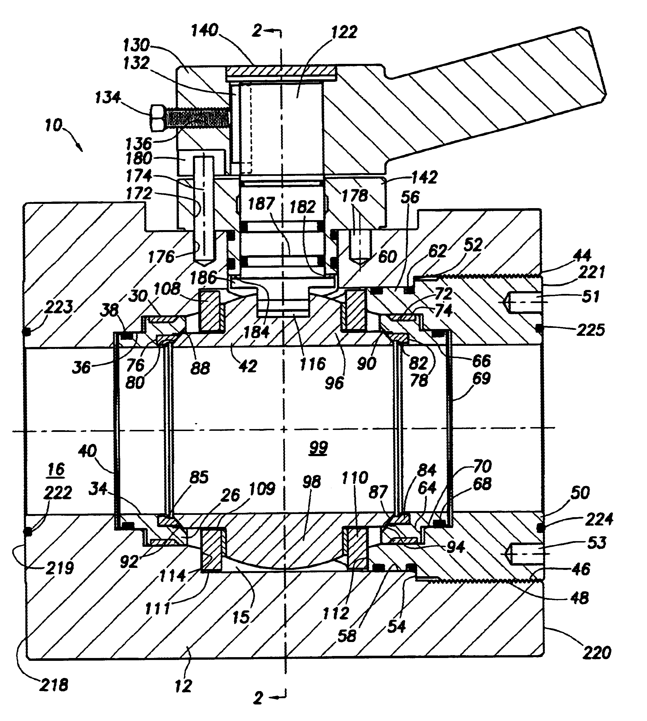
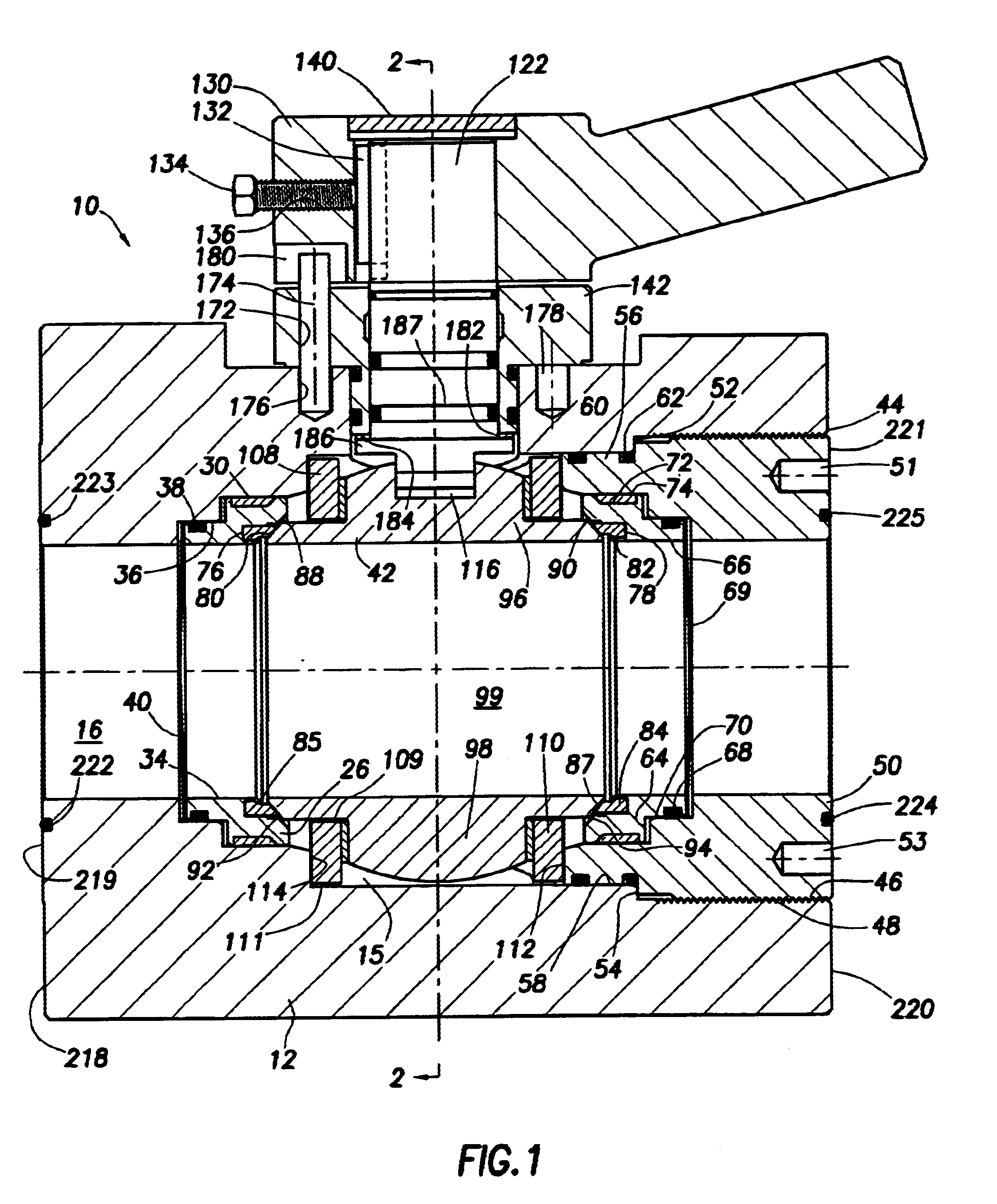
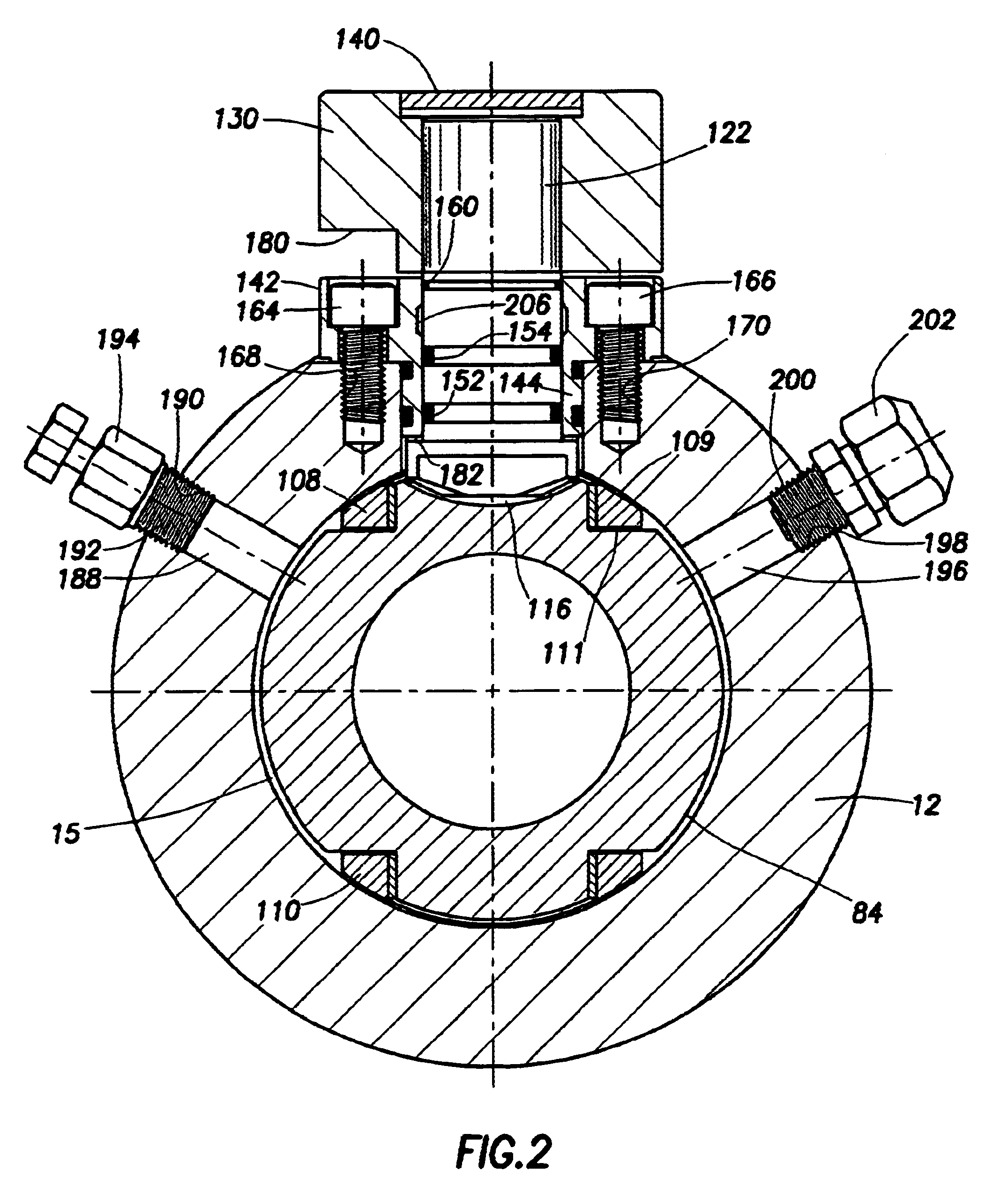
Referring now to the drawings and first to FIGS. 1, 2, 3, 4 and 5 a compact manifold ball valve embodying the principles of the present invention is shown generally at 10 and incorporates a valve body 12 having a first axial end 11 and a second axial end 13. The valve body 12 defines an internal valve chamber 15 and a flow passage 16 in communication with the valve chamber 15. The valve body 12 defines a cylindrical bore 18 forming a bonnet and actuating stem receptacle 20 which is also in communication with the valve chamber 14 as is evident from the exploded view of FIG. 4.

The valve body 12 also defines a stepped internal seat recess 22 within which is located an annular seat assembly 24. The seat assembly 24 has a circular seat body structure 26 having an outer peripheral seal groove 28 within which is received a circular heat resistant seal 30 having sealing engagement with a circular sealing surface 32 of the seat recess 22. The annular seat assembly 24 also defines a circular ...


PUM


Abstract

A compact manifold ball valve having a valve body defining a valve chamber and having first and second ends and a first flow passage intersecting the valve chamber a cylindrical sealing surface defining a bonnet and valve stem passage also intersecting the valve chamber. A seat and ball retainer is threaded into the second end of the valve body and provides for support and positioning of a pair of trunnion support elements and a pair of seat assemblies. A valve ball having opposed trunnions is rotatable between open and closed positions within the valve chamber and is supported by the trunnion supports. A valve stem and bonnet assembly is secured and sealed to said valve body and is actuated to rotate the valve ball for opening and closing thereof. The valve seats are capable of metal-to-metal sealing with the valve ball in the event of heat destruction of said face seals to provide the valve with a fire-safe character. The seats incorporate high temperature graphite filament seals for fire-safe sealing between the valve seats and valve body in the event of heat destruction of said back seals. Other internal metal surfaces are arranged for metal-to-metal fire-safe sealing in the event the primary seals are destroyed by heat.

Description

1. Field of the InventionThis invention relates generally to ball valves for use particularly in conduit manifold systems and more particularly concerns a compact manifold ball valve having fire-safe features to maintain the sealing integrity thereof when the valve has been subjected to sufficient heat for a sufficient period of time to destroy the elastomer and polymer sealing elements thereof. More particularly, the present invention is directed to a ball valve mechanism having a ball defining integral trunnions which are supported for rotation within the valve chamber by trunnion support and bearing assemblies which are free to shift and permit the valve ball element to be self-centering with respect to either of two seat assemblies that are disposed within seat pockets that are also defined by the valve body. Additionally, the present invention concerns a compact trunnion type ball valve having an actuating stem and a seat retainer which are blow-out proof even under conditions ...

Claims


Application Information

Patent Timeline
IPC IPC(8): F16K5/06
CPCF16K5/0673F16K5/0642
Inventor STUNKARD, GERALD A.
Owner ARRAY HLDG
Why Eureka
Try Eureka