Member arranged to act between two in relation to each other movable parts of a vehicle

a technology of a member and a rod is applied in the direction of mechanical equipment, transportation and packaging, and gearing. it can solve the problems of a large mass, a large rotor motion, and a large amount of maintenan

Inactive Publication Date: 2004-01-06
DAIMLER AG
View PDF17 Cites 14 Cited by
  • Summary
  • Abstract
  • Description
  • Claims
  • Application Information

AI Technical Summary

Problems solved by technology

A disadvantage with the hydraulic or pneumatic members is that they are subject to faults and that they require a great deal of maintenance.
A disadvantage with the known construction is that the motions of the rotor are transferred to the rod, which has a relatively large mass.
Such a transmission comprises a

Method used


Image

  • Member arranged to act between two in relation to each other movable parts of a vehicle
  • Member arranged to act between two in relation to each other movable parts of a vehicle
  • Member arranged to act between two in relation to each other movable parts of a vehicle

Examples


Embodiment Construction

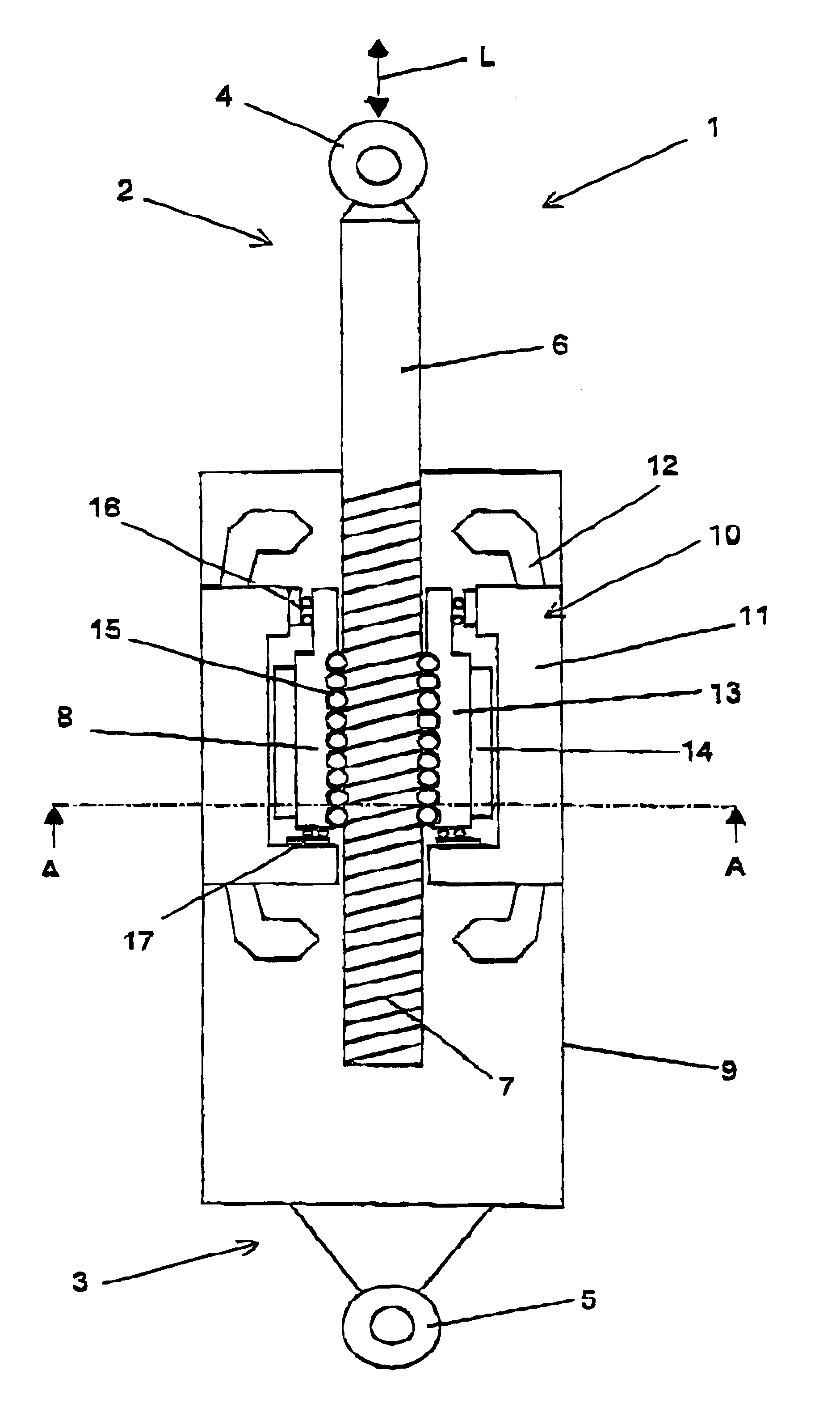
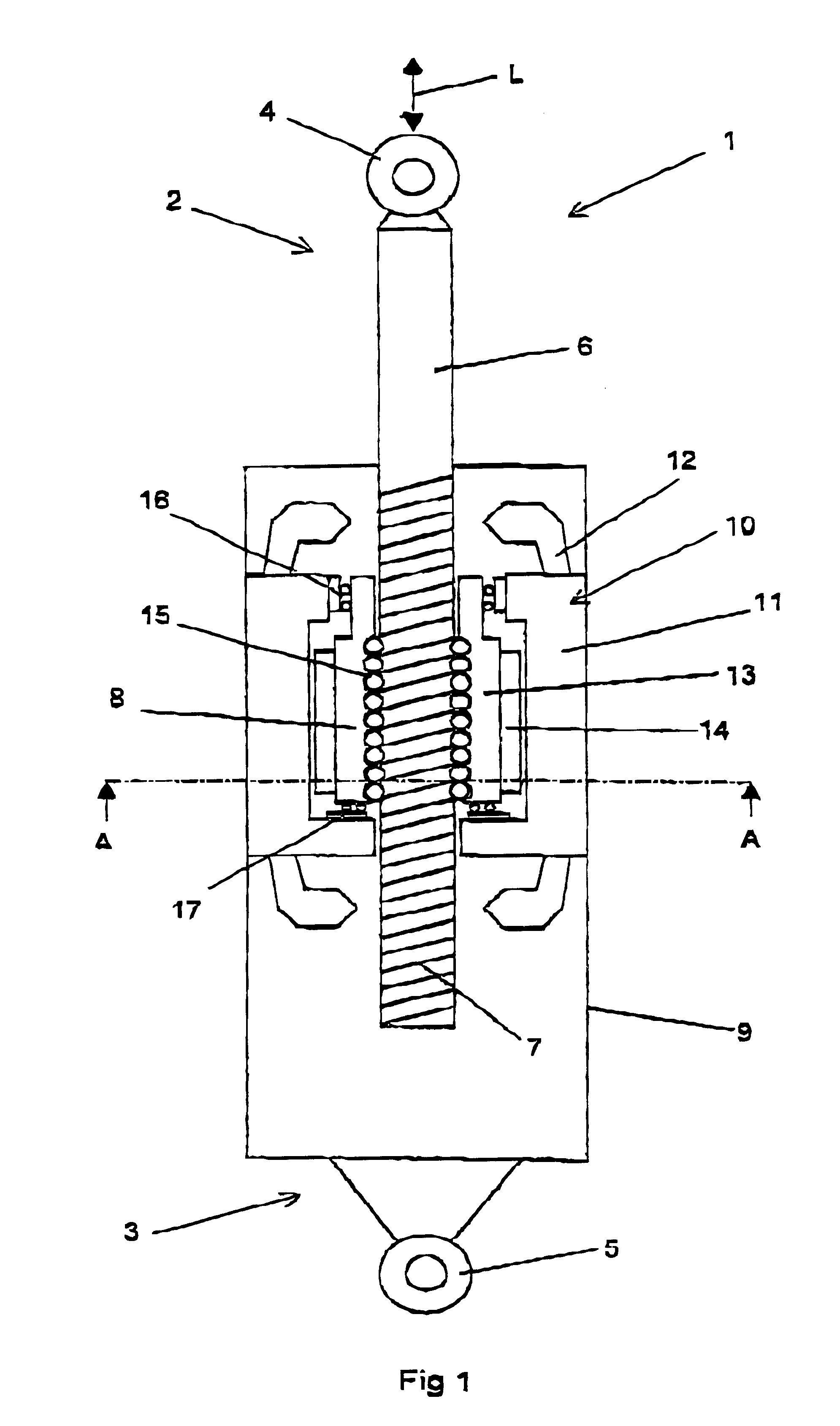
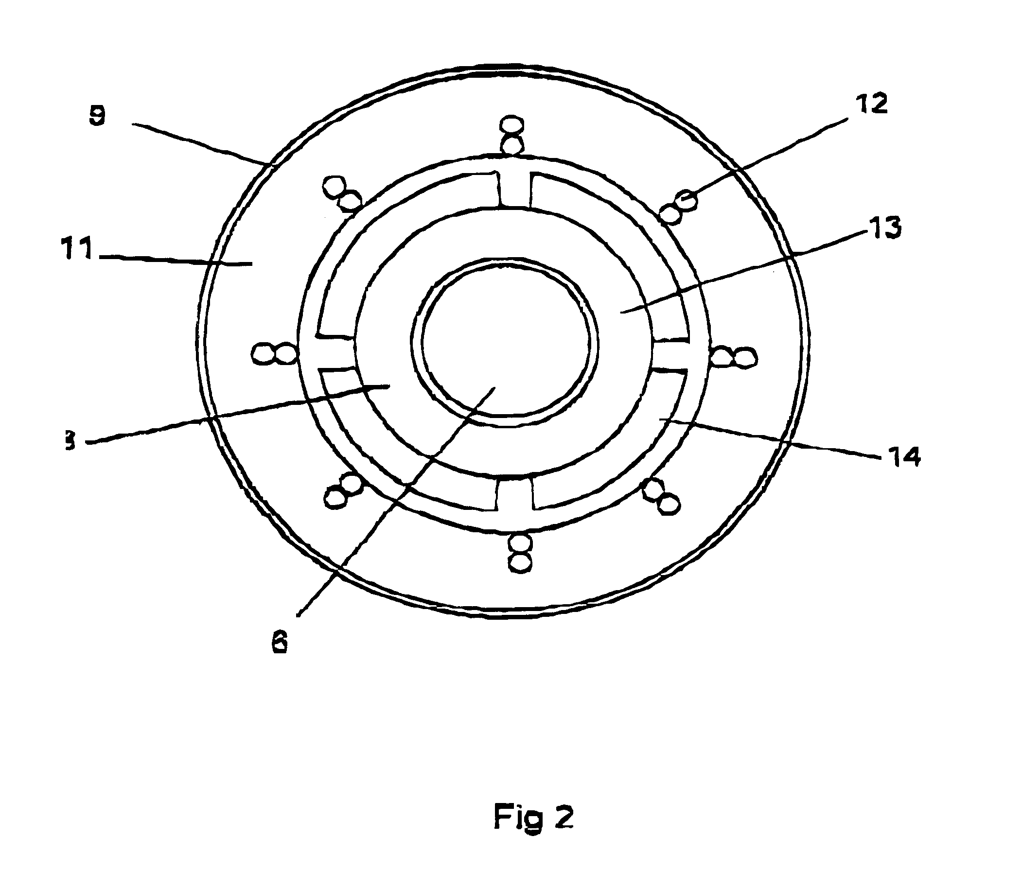
FIGS. 1 and 2 show a member 1 arranged to act between two parts of a vehicle which are movable in relation to each other. The member 1 comprises a first portion 2 and a second portion 3, which are variable in length in relation to each other in order to influence the position of the vehicle parts which are movable in relation to each other. The first portion 2 is connectable to one of said vehicle parts by means of a first ring-shaped member 4 and the second portion 3 is connectable to the other vehicle part by means of a second ring-shaped member 5. The first portion 2 comprises an elongated rod 6 having external threads 7 while the second portion 3 comprises a nut 8 rotatably provided on the rod 6. Thereby, the length of the member 1 is variable in an axial direction L under a rotary motion between the rod 6 and nut 8. The second portion 3 comprises a cylindrical portion 9 having an inner cavity arranged to receive an electric rotor machine 10. The electric rotor machine 10 compri...


PUM


Abstract

The present invention relates to a member (1) arranged to act between two parts of a vehicle which are movable in relation to each other. The member (1) comprises a first portion (2) having an elongated rod (6) with external threads (7) and a second portion (3) having a nut (8) rotatably provided on the rod (6) so that the length of the member (1) during a rotary motion between the rod (6) and nut (8) is variable in an axial direction (L). An electric rotor machine (10), having a stator (11) and a rotor (13) which is rigidly connected to said nut (8), is arranged to influence said rotary motion. The rotor (13) and nut (18) are so positioned in relation to each other that at least a radial plane with respect to the axial direction (L) extends both through the rotor (13) and the nut (8).

Description

TECHNICAL FIELD OF THE INVENTION AND PRIOR ARTThe present invention relates to a member arranged to act between two parts of a vehicle which are movable in relation to each other, wherein the member extends between said parts and comprises a first portion connectable to the first part of the vehicle and a second portion connectable to the second part of the vehicle, wherein the first portion comprises an elongated rod having external threads and the second portion a nut provided rotatably on the rod so that the length of the member, during a rotary motion between the rod and the nut, is variable in an axial direction, wherein an electric rotor machine having a stator and a rotor is arranged to influence said rotary motion and wherein the rotor and the nut are so located in relation to each other that at least one radial plane with respect to the axial direction extends both through the rotor and the nut.In order to obtain a good comfort for passengers in a trackbound vehicle, it is ...

Claims


Application Information

Patent Timeline
IPC IPC(8): B62D33/06B61F5/22B61F5/02H02K7/06F16H25/20
CPCB61F5/22B62D33/0608H02K7/06F16H25/20Y10T74/1836Y10T74/18664F16H2025/2075
Inventor ENGSTROM, JORGENKJELLQVIST, PETER
Owner DAIMLER AG
Why Eureka
Try Eureka