Method for controlling array antenna equipped with single radiating element and a plurality of parasitic elements

a technology of array antenna and parasitic element, which is applied in the direction of antenna array, electrical apparatus, antennas, etc., can solve the problems of increasing the number of calculations, the inability to observe any signal on a passive element, and the inability of most methods prepared for conventional adaptive arrays to directly apply to the espar antenna

Inactive Publication Date: 2004-01-13
ATR ADVANCED TELECOMM RES INST INT
View PDF4 Cites 33 Cited by
  • Summary
  • Abstract
  • Description
  • Claims
  • Application Information

AI Technical Summary

Benefits of technology

Also, a second object of the invention is to provide a method for controlling an ESPAR antenna which has solved the above problems, that is, a method for controlling an array antenna, capable of remarkably reducing the convergence time as compared with that of the related art methods, and capable of achieving adaptive control so as to direct the main beam toward a desired wave and to direct the null(s) thereof toward an interference wave(s), with less calculation amount.
Further, a third object of the invention is to provide a method for controlling an ESPAR antenna capable of solving the above problems, that is, a method for controlling an array antenna, capable of obtaining a successful estimation function value and obtaining a successful convergence value at a higher speed with less iterations, as compared with those of the related art methods, for directing the main beam toward a desired wave and directing the null(s) thereof toward an interference wave(s).

Problems solved by technology

However, in the case of the ESPAR antennas, it is impossible to observe any signal on a passive element.
In other words, most methods prepared for conventional adaptive arrays cannot be directly applied to the ESPAR antenna.
In the case of the ESPAR antenna, it is necessary to provide a training sequence at least (M+1) times longer than that of conventional adaptive arrays, and this leads to such a problem as increase in calculation quantity.
Also, with the use of the first related art method, since a relatively large amount of trials is required for pursuing an optimum solution, and this leads to such a problem as longer convergence time.
However, this method has such a problem that since the succeeding trial is independent of the preceding trial, nothing has been trained when a trial is completed.

Method used


Image

  • Method for controlling array antenna equipped with single radiating element and a plurality of parasitic elements
  • Method for controlling array antenna equipped with single radiating element and a plurality of parasitic elements
  • Method for controlling array antenna equipped with single radiating element and a plurality of parasitic elements

Examples


second preferred embodiment

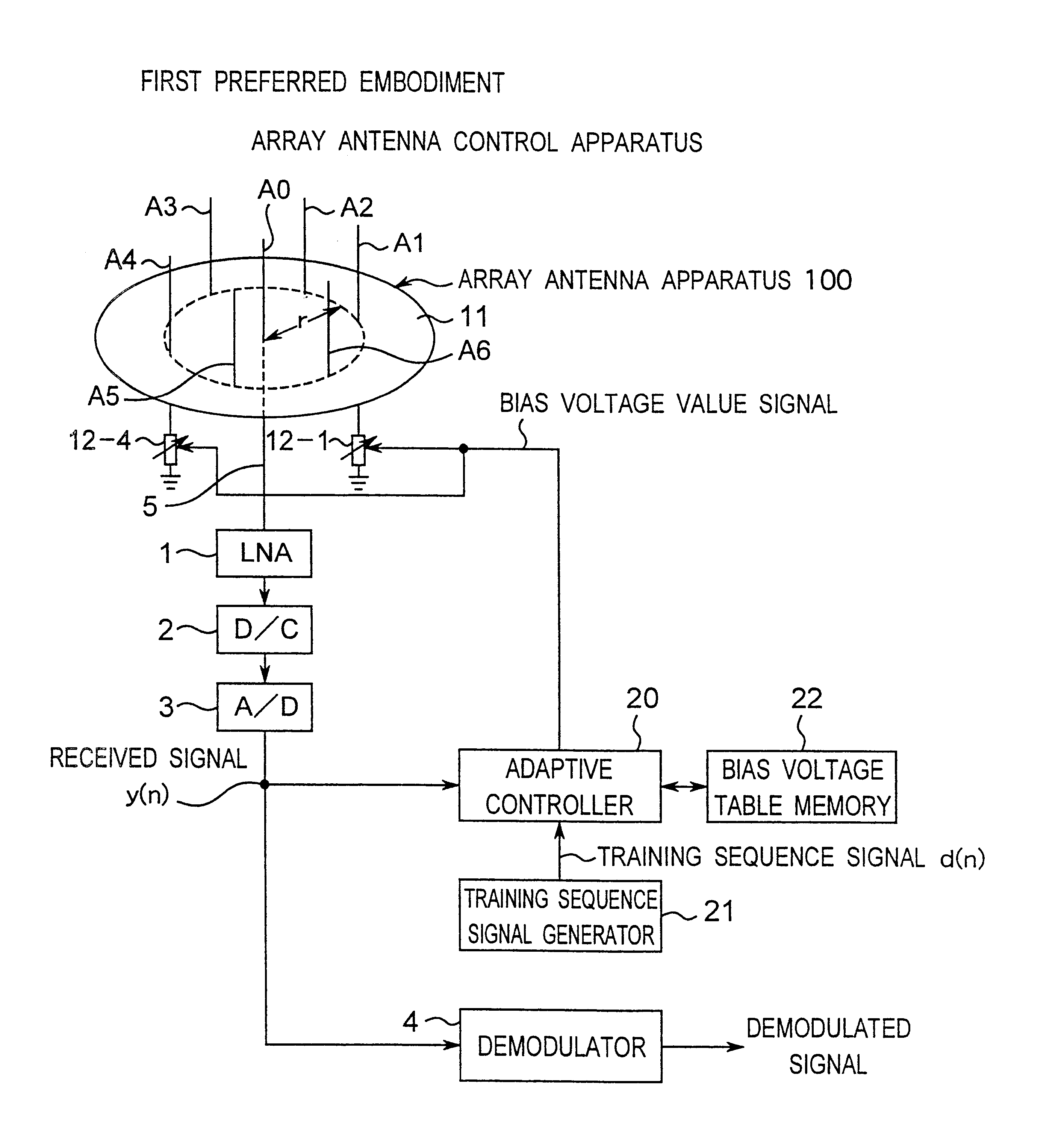
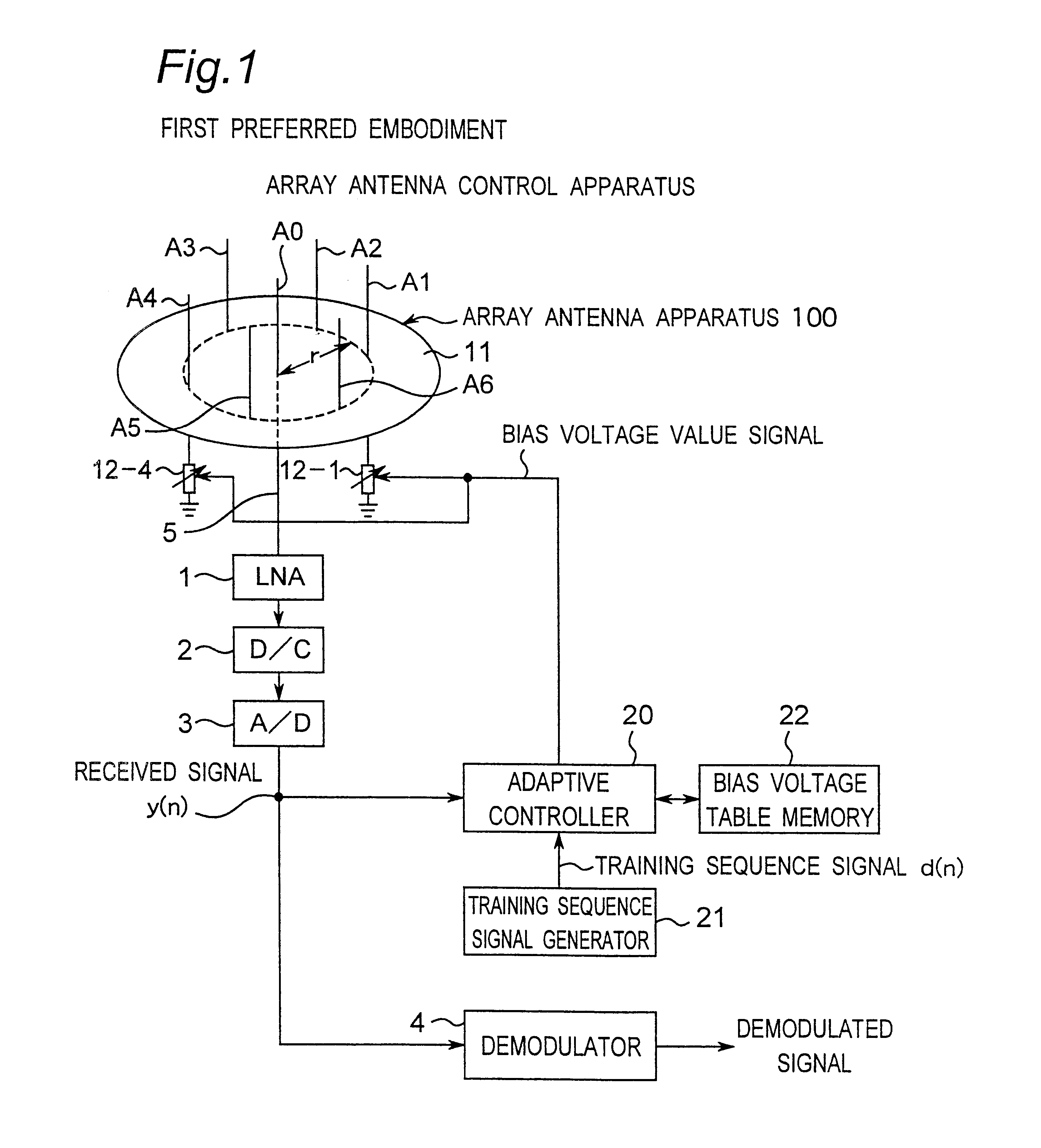
FIG. 14 is a block diagram showing a configuration of an array antenna control apparatus which is a second preferred embodiment according to the present invention. The array antenna control apparatus of the present preferred embodiment, as shown in FIG. 14, includes: an array antenna apparatus 100 which is the ESPAR antenna and which is equipped with one radiating element A0 and six parasitic elements A1 to A6; an adaptive controller 20A; a training sequence signal generator 21; and a control voltage table memory 30 connected to the adaptive controller 20A. The adaptive controller of the second preferred embodiment is characterized in that the adaptive controller 20A is provided instead of the adaptive controller 20, as compared with the array antenna control apparatus of the first preferred embodiment shown in FIG. 1. The following description will be focused mainly on this difference point.

In this case, the adaptive controller 20A, which is implemented by a computer or the other d...

third preferred embodiment

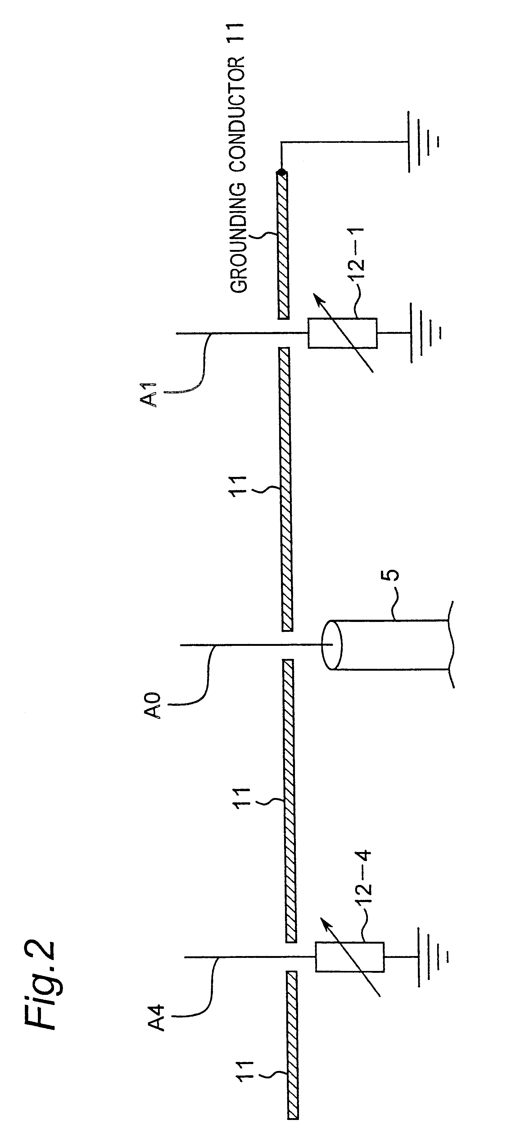
FIG. 27 is a block diagram showing a configuration of an array antenna control apparatus which is a third preferred embodiment according to the present invention. The array antenna control apparatus of the present preferred embodiment, as shown in FIG. 27, includes: an array antenna apparatus 100 which is the ESPAR antenna and which is equipped with one radiating element A0, six parasitic elements A1 to A6 having variable-reactance elements 12-1 to 12-6 loaded thereon, respectively; a grounding conductor 11; an adaptive controller 20B; and a training sequence signal generator 21. This third preferred embodiment is characterized in that the adaptive controller 20B is provided instead of the adaptive controller 20 shown in FIG. 1, as compared with the first preferred embodiment. The following description will be focused mainly on this difference point.

In this case, the adaptive controller 20B, which is implemented by a computer or the other digital computing machine as an example, is ...

fourth preferred embodiment

FIG. 51 is a block diagram showing a configuration of an array antenna control apparatus which is a fourth preferred embodiment according to the present invention. The array antenna control apparatus of the present preferred embodiment, as shown in FIG. 51, includes: an array antenna apparatus 100 which is the ESPAR antenna and which is equipped with one radiating element A0, six parasitic elements A1 to A6 having variable-reactance elements 12-1 to 12-6 loaded thereon, respectively, and. a grounding conductor 11; an adaptive controller 20C; and a training sequence signal generator 21. This fourth preferred embodiment is characterized in that the adaptive controller 20C is provided instead of the adaptive controller 20, as compared with the first preferred embodiment shown in FIG. 1. The following description will be focused mainly on this difference point.

In this case, the adaptive controller 20C, which is implemented by a computer or the other digital computing machine as an examp...


PUM


Abstract

An adaptive controller for an ESPAR antenna randomly perturbs a bias voltage vector V(n) composed of elements of bias voltage values Vm by a random vector R(n) generated by a random number generator, compares an objective function value J(n) of a cross correlation coefficient for a bias voltage vector V(n) before the perturbation with an objective function value J(n+1) of a cross correlation coefficient for a bias voltage vector V(n+1) after the perturbation, and selects and sets the bias voltage Vm corresponding to that when the cross correlation coefficient increases before and after the perturbation. Then the adaptive controller repeats the random perturbation and setting from the bias voltage of respective varactor diodes. This leads to that it is not necessary to provide a long training sequence signal, and the control process can be executed with learning so that a performance can be improved every iteration for search.

Description

1. Field of the InventionThe present invention relates to a method for controlling an array antenna capable of changing a directivity characteristic of an array antenna apparatus including a plurality of antenna elements. In particular, the invention relates to a method for controlling an array antenna capable of adaptively changing an directivity characteristic of an electronically steerable passive array radiator (ESPAR) antenna (hereinafter, referred to as an ESPAR antenna) equipped with a single radiating element and a plurality of parasitic elements.2. Description of the Related ArtAn ESPAR antennas of related art is proposed in, for example, U.S. Pat. No. 6,407,719, the Related art document 1 of T. Ohira et al., "Electronically steerable passive array radiator antennas for low-cost analog adaptive beamforming", 2000 IEEE International Conference on Phased Array System &, Technology pp. 101-104, Dana point, Calif., May 21-25, 2000, and the Japanese Patent Laid-Open Publication ...

Claims


Application Information

Patent Timeline
Patent Type & Authority Patents(United States)
IPC IPC(8): H01Q19/32H01Q19/00H01Q3/24
CPCH01Q3/24H01Q19/32
Inventor CHENG, JUNHIRATA, AKIFUMIOHIRA, TAKASHIIIGUSA, KYOUICHINAKAJI, TAKUYOKIKUMA, NOBUYOSHIINAGAKI, NAOKI
Owner ATR ADVANCED TELECOMM RES INST INT
Why Eureka
Try Eureka