
Power efficiency circuit

a power efficiency circuit and circuit technology, applied in the direction of engine lubrication, liquid/fluent solid measurement, reradiation, etc., can solve the problems of limiting, electric energy not available in a sufficient amount, and equipment which is to be located in explosive environments subject to authority demands

Inactive Publication Date: 2004-01-20
ROSEMOUNT TANK RADAR
View PDF13 Cites 55 Cited by
  • Summary
  • Abstract
  • Description
  • Claims
  • Application Information

AI Technical Summary

Problems solved by technology

However, microwave transmitters for level gauging in the process control industry have often required a separate power source.
Equipment which is to be located in explosive environments is subjected to authority demands.
Intrinsic safe means that the construction in itself is designed in such a way, that electric energy is not available in a sufficient amount to generate a spark, which can set fire to an explosive gas surrounding the construction.
As a result there is required a barrier that limits, with high security, energies possibly available at wave guides and antenna parts.
Limitations arise when the power required by the gauge exceeds the available power from the loop.
If the available voltage for the gauge is below the required lift-off voltage at said certain current the power is not high enough to energize the gauge.
A drawback with this solution is that the transmission / receive unit is unavailable during energy storing cycles.
A drawback of the disclosure is further that a loop current setting means is connected in series with the transducer, whereby the full loop current is passing said setting means and thus imparting a voltage drop across said setting means in the loop.
Charging electrical storage means, such as a capacitor or a battery, in the gauge with sensed excessive power.

Method used


Image

  • Power efficiency circuit
  • Power efficiency circuit
  • Power efficiency circuit

Examples


Embodiment Construction

Examples of embodiments of the invention are here described with support of the enclosed figures.

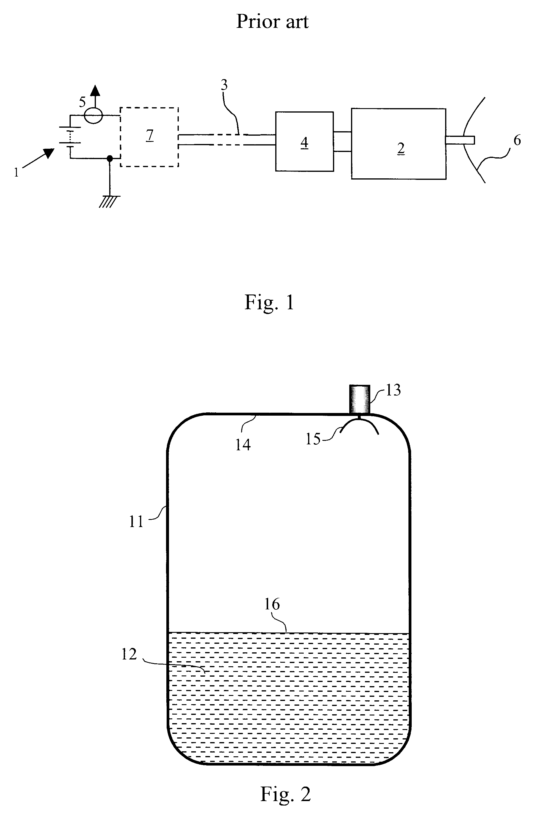
An application of a radar level gauge is shown in FIG. 2. A tank 11 is used for storing a product 12. The product may be such as oil, refined products, chemicals and liquid gas, or may be a material in powder form. Radar 13 is attached to the roof 14 of the tank 11. A microwave beam is transmitted from the radar via an antenna 15 at the interior of the tank. The transmitted beam is reflected from the surface 16 of the product and is received by the antenna 15. By means of a comparison and evaluating of the time lap between transmitted and reflected beam in a measuring and controlling unit, a determination of the level of the product surface 16 in a known manner is performed. The microwave may be transmitted from the antenna a free radiated beam or via a wave guide (not shown), which communicates with the product. The radar level gauge as shown in FIG. 2 is only used as an example.

The loc...


PUM


Abstract

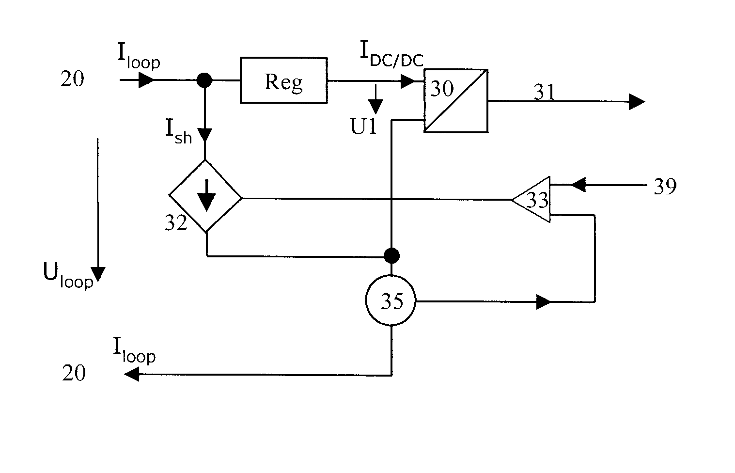
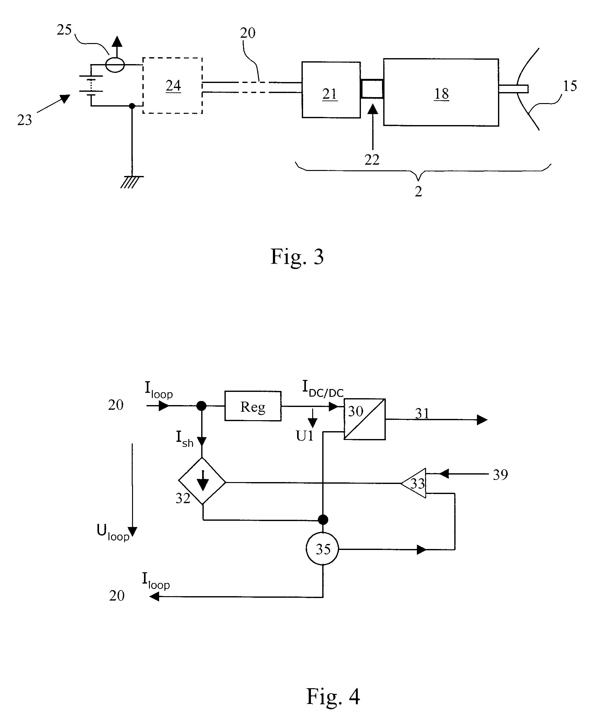
A radar level gauge for measuring a level of a surface of a product in a tank having a two-wire process control loop, output circuitry coupled to the two-wire process control loop for setting in the loop a desired value of a loop current (Iloop) corresponding to the product level, a power supply circuitry coupled to the two-wire process control loop for receiving power from the loop and being a source of power for a microwave source, a microwave receiver, a measurement circuitry and the output circuitry and including a converter for transferring power from the loop to said power supply circuitry by means of feeding a first current (IDC / DC) from the loop to the power supply circuitry, a current generator included in said output circuitry for generating in parallel to said first current a second current (Ish) in the loop for maintaining said loop current at a value corresponding to said product level and a sensing circuit for determining the value of said second current and having an output indicative of the value of said second current.

Description

The present invention relates to level measurement in industrial processes, wherein the invention is used for measurement of product level in a storage tank of the type used in industrial applications using a microwave level gauge. More specifically, the present invention relates to a device and a method for efficient use of power provided to the gauge from a two-wire process control loop.BACKGROUND AND RELATED ARTInstrumentation for the measurement of product level (either liquids or solids) in storage vessels is evolving from contact measurement techniques, such as tape and float, to non-conduct techniques. One technology is based on the use of microwaves, which involves transmitting microwaves towards the product surface and receiving reflected microwaves from the surface. The reflected microwaves are analyzed to determine the distance that they have travelled. Knowledge of the distance travelled allows determination of the product level.Often used in the process control industry...

Claims


Application Information

Patent Timeline
IPC IPC(8): G01F23/284
CPCG01F23/284
Inventor NILSSON, VALTERABRAHAMSSON, PAR
Owner ROSEMOUNT TANK RADAR
Learn More