Jet flow control for hydrotherapy spa

Inactive Publication Date: 2004-01-27
MAY MFG
View PDF18 Cites 23 Cited by
  • Summary
  • Abstract
  • Description
  • Claims
  • Application Information

AI Technical Summary

Benefits of technology

An advantage of the invention is that by providing a motor for driving the hydrotherapy pump at each therapy station, less electricity is consumed than is consumed by a conventional spa having larger motors, each of which drives a pump for a plurality of therapy stations. Another advantage of the invention i

Problems solved by technology

Consequently, the system requires piping of significant length, diameter and complexity, and usually a number of diverter valves.
Because of the significant lengths of piping between the pumps and the jets, significant frictional losses are encountered.
Such assemblies are limited to spas having only a few jets and would not

Method used


Image

  • Jet flow control for hydrotherapy spa
  • Jet flow control for hydrotherapy spa
  • Jet flow control for hydrotherapy spa

Examples


Example

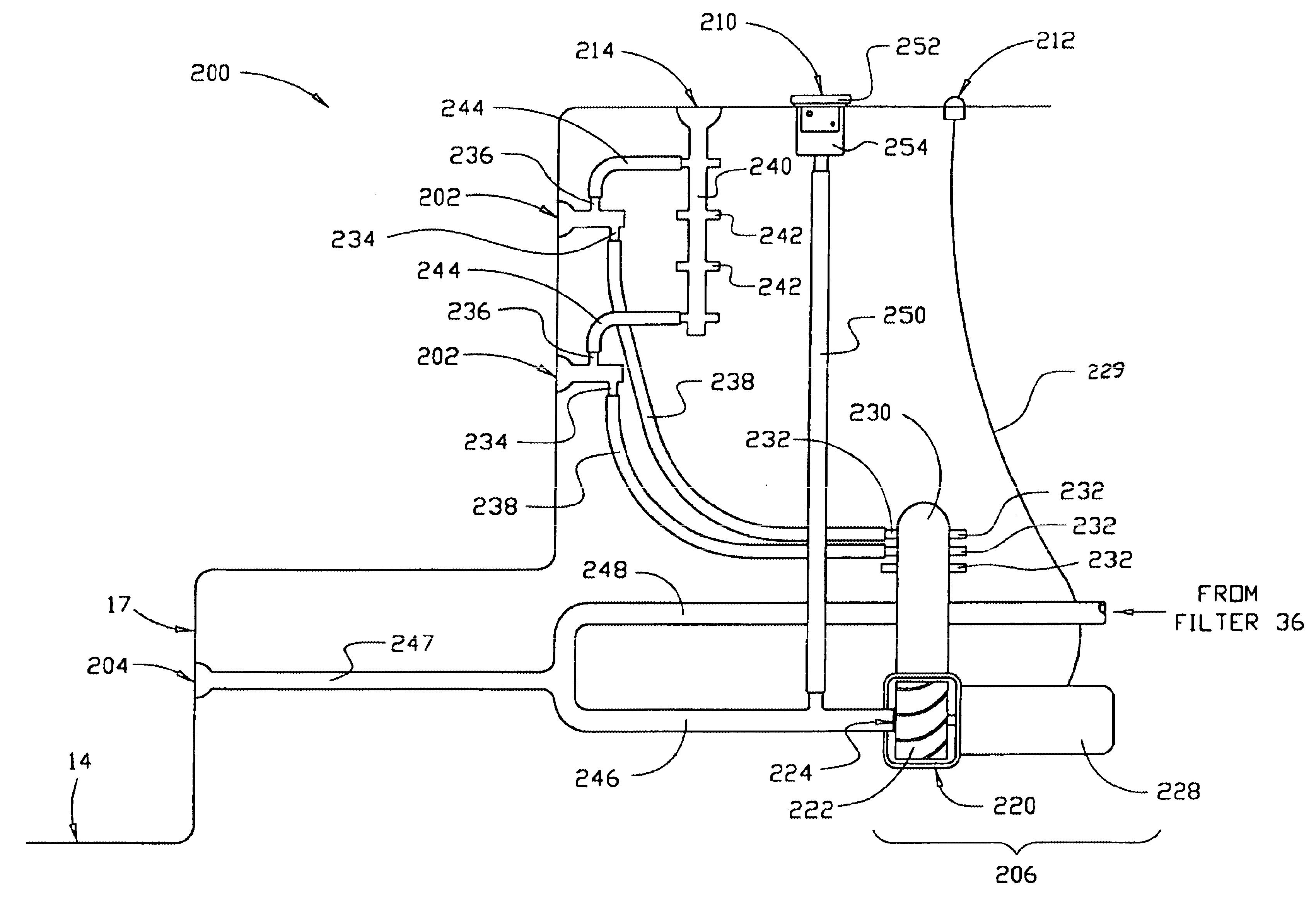
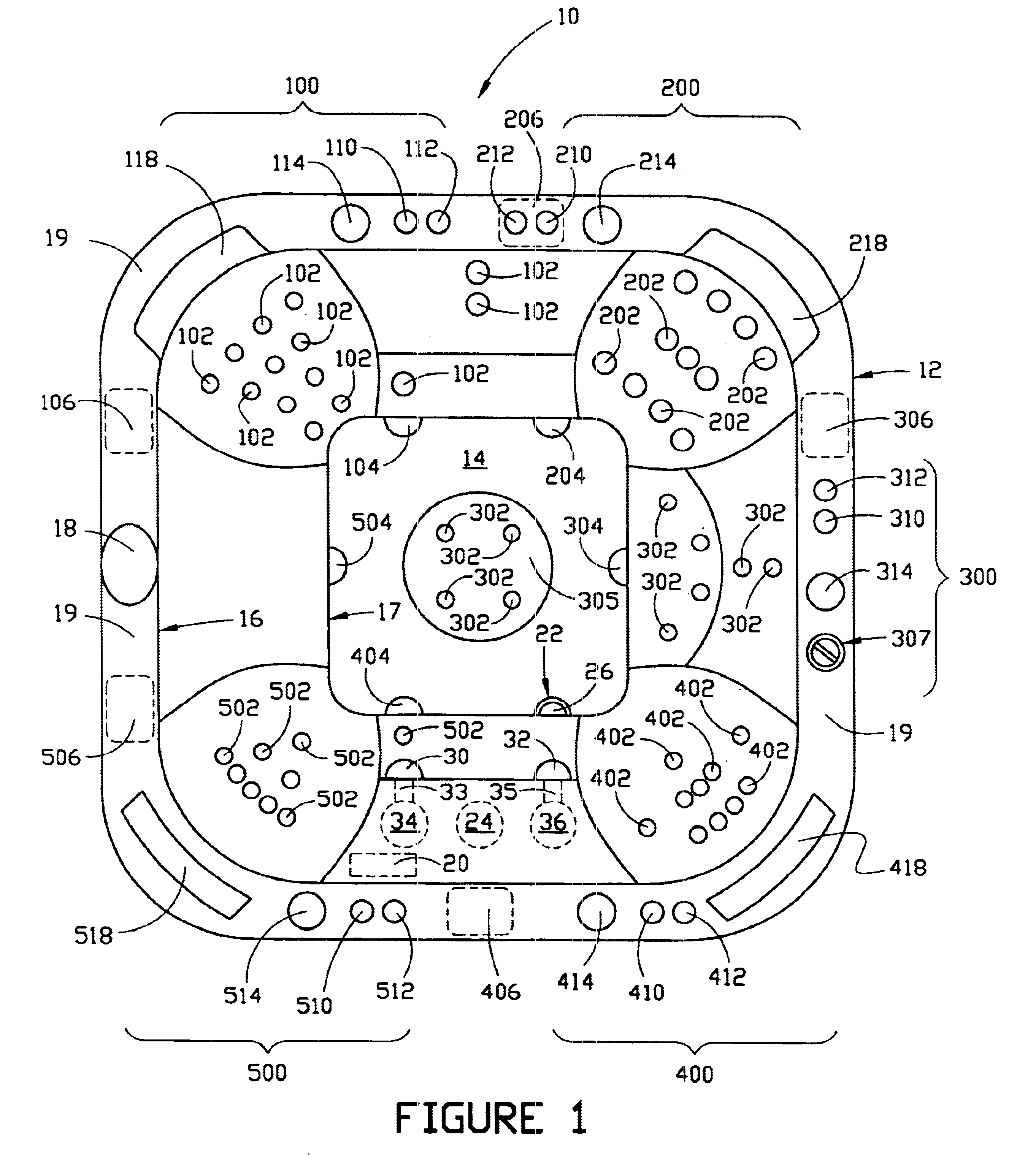
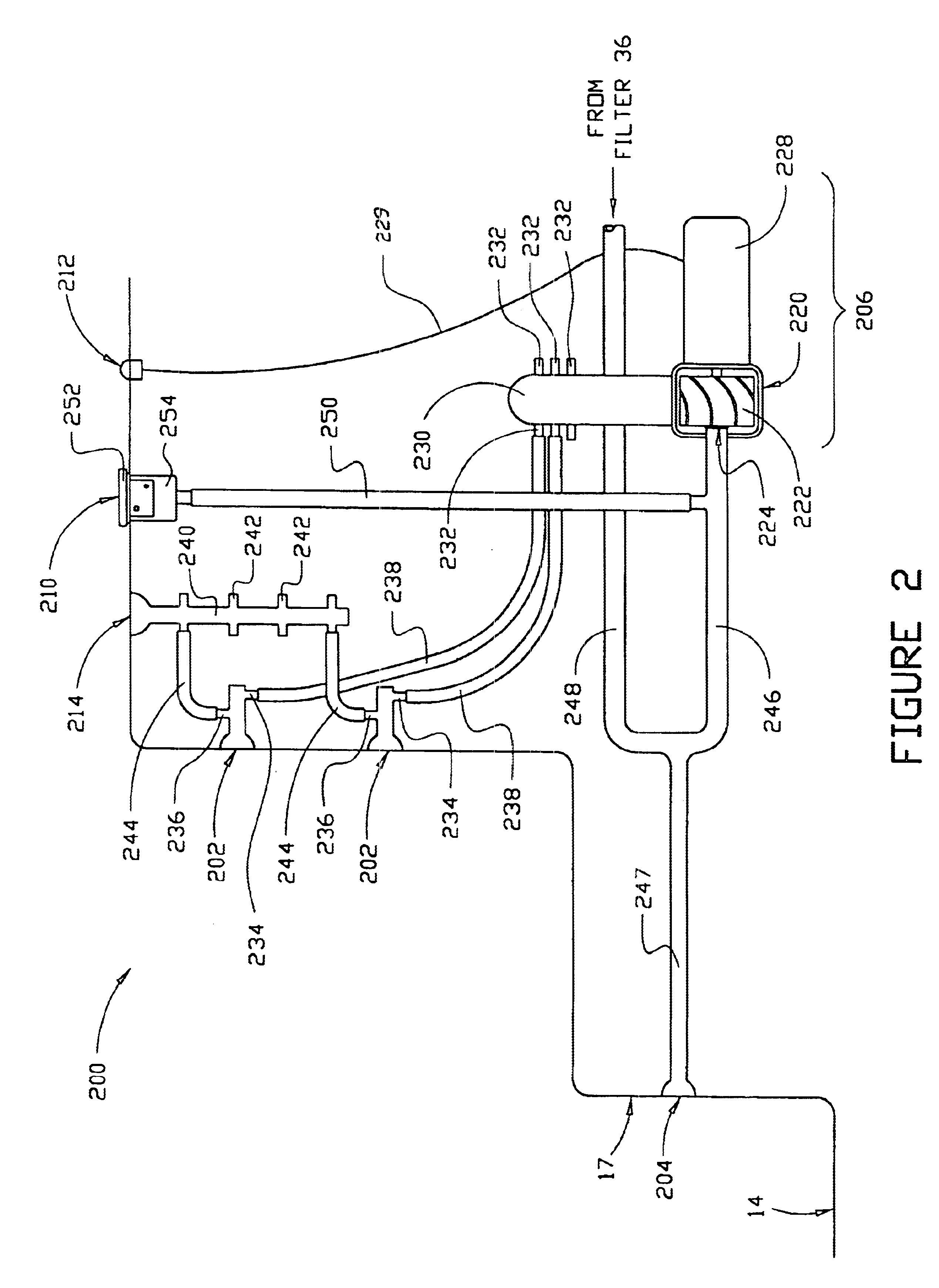
Referring now to the drawings, FIG. 1 illustrates referred spa 10, which comprises a fluid enclosure 12 having a floor 14 and an upstanding sidewall 16. The floor is located at the bottom of and is surrounded by upstanding footwell wall 17. The enclosure shell of preferred spa 10 is constructed of conventional materials. Spa 10 includes five therapy stations, designated generally as stations 100, 200, 300, 400 and 500, each of which includes a hydrotherapy assembly according to the invention.

Preferred main control panel 18 is mounted in upper surface 19, and includes controls for the power supply to all pumps, controls for water heaters (not shown), controls for lights (not shown), child safety controls and controls for circulating pump 20. Preferably, circulating pump 20 is a small pump (typically 1 / 32 HP) that circulates water from the enclosure through fluid inlet 22, through circulating filter 24, a heating and sanitation unit (not shown), and back to the enclosure through fluid...


PUM


Abstract

A spa comprised of a fluid enclosure having a floor and an upstanding sidewall includes a plurality of therapy stations within the enclosure. Each therapy station includes a hydrotherapy assembly and each such assembly includes a plurality of fluid jets in the floor or sidewall of the enclosure and a fluid inlet through the floor or sidewall of the enclosure. Each hydrotherapy assembly also includes a fluid pump having a suction port that is in fluid communication with the inlet and a discharge port that is in fluid communication with the jets. The pump is adapted to move fluid from the enclosure through the fluid inlet and suction port and back through the discharge port and the jets into the enclosure. A variable flow controller is also provided for each hydrotherapy station, which controller is adapted to control the flow of fluid from the discharge port of the pump through the jets into the enclosure.

Description

This invention relates generally to spas having a plurality of therapy stations each of which includes a plurality of hydrotherapy jets. More particularly, the invention relates to a water distribution and jet flow control system for such a spa.BACKGROUND AND DESCRIPTION OF THE PRIOR ARTBathing appliances in the nature of spas or hot tubs have become commercially successful. These spas are typically constructed as a molded shell to form a water containment or fluid enclosure having a footwell or floor and an upstanding sidewall. Molded within the enclosure are a plurality of therapy stations which may include seats or platforms for reclining. The shell is typically constructed of fiberglass, plastic or a similar material, or a composite of such materials. One or more pumps are usually placed under the shell to draw water from the enclosure and discharge it, usually with air, into the enclosure through a plurality of nozzles or jets of various types. The jets are usually mounted thro...

Claims


Application Information

Patent Timeline
IPC IPC(8): A47K3/10A61H33/02
CPCA61H33/60A61H33/02A61H2033/022A61H2201/1207
Inventor MAY, TOM M.HENDRICKS, GEORGE L.ROMANO, SCOTT A.
Owner MAY MFG
Why Eureka
Try Eureka