Method and apparatus for removing fluids from drill cuttings

a technology of fluid removal and drill cuttings, which is applied in the direction of filtration separation, separation process, and borehole/well accessories, etc., can solve the problems of affecting the performance of drilling mud, recirculation of drill cuttings can also increase the wear of mud pumps and other mechanical equipment, and oil-based muds and synthetic muds can be environmentally harmful

Inactive Publication Date: 2004-01-27
HALLIBURTON ENERGY SERVICES INC
View PDF21 Cites 26 Cited by
  • Summary
  • Abstract
  • Description
  • Claims
  • Application Information

AI Technical Summary

Benefits of technology

It is yet another object of the present invention to provide a means of separating fluids from drill cuttings which utilizes a relatively small amount of equipment and, therefore, has minimal space requirements.
It is often beneficial to agitate fluids-laden drill cuttings deposited on the outer surface of said cylindrical wire-wrapped screen. In the preferred embodiment, a reciprocating scraper is positioned along the upper surface of said cylindrical wire-wrapped screen. Said reciprocating scraper moves in a path of travel parallel to the longitudinal axis of said cylindrical wire-wrapped screen. As fluids-laden drill cuttings are deposited on the upper portion of said cylindrical wire-wrapped screen, said reciprocating scraper even the piled cuttings, reducing the angle of repose and speeding the spreading of such cuttings over the upper surface of said cylindrical wire-wrapped screen. Said reciprocating scraper also helps to clear the surface of the cylindrical screen, thereby improving effectiveness of the fluid separation.

Problems solved by technology

This often leads to problems, because such drilled solids can dramatically alter the characteristics and performance of the drilling mud.
Further, recirculation of drill cuttings can also increase wear in mud pumps and other mechanical equipment used in the drilling process.
Unfortunately, in most instances the disposal of drill cuttings can present a number of different problems.
However, even though drill cuttings leaving a shale shaker have been separated from a well's effluent mud stream, such cuttings nonetheless typically include entrained and / or adherent mud and other fluids which could be damaging to the environment.
Many of these additives, oil-based muds and synthetic-based muds can be environmentally harmful.
Thus, it is often undesirable and a violation of environmental regulations to release such fluid-laden cuttings directly into the surrounding environment.
While this solution can be generally functional, it is not without significant problems.
One major problem associated with the off-site disposal of drill cuttings is increased cost.
Such equipment is often in the form of complicated and elaborate conveyors, augers and / or vacuum units.
All of this added equipment and labor increases the costs associated with the drilling process.
Another major problem associated with off-site disposal of fluids-laden drill cuttings is the use of valuable rig space.
In most instances, cuttings disposal equipment takes up a great deal of a rig's available work area.
For example, large storage boxes, which must be loaded on and off a rig, take up a significant amount of space.
Similarly, equipment used to move such cuttings from a rig's shale shaker to cuttings boxes can also take up a great deal of space.
This additional equipment can present logistical and / or safety problems on many rigs.
Another problem associated with off-site disposal of drill cuttings is environmental impact.
Such off-site disposal of drill cuttings does not necessarily guarantee an overall reduction or elimination of environmental contamination.
As a result, the overall impact on the environment of offsite disposal can be significant.
However, attempts at washing or otherwise treating drill cuttings on location have also proven to be problematic.
Frequently, existing methods of washing drill cuttings require large amounts of equipment, which can cause space problems on most drilling rigs and add to the overall expense of a drilling project.
Perhaps most significantly, washed drill cuttings are seldom clean enough for discharge directly into the surrounding environment.

Method used


Image

  • Method and apparatus for removing fluids from drill cuttings
  • Method and apparatus for removing fluids from drill cuttings
  • Method and apparatus for removing fluids from drill cuttings

Examples


Embodiment Construction

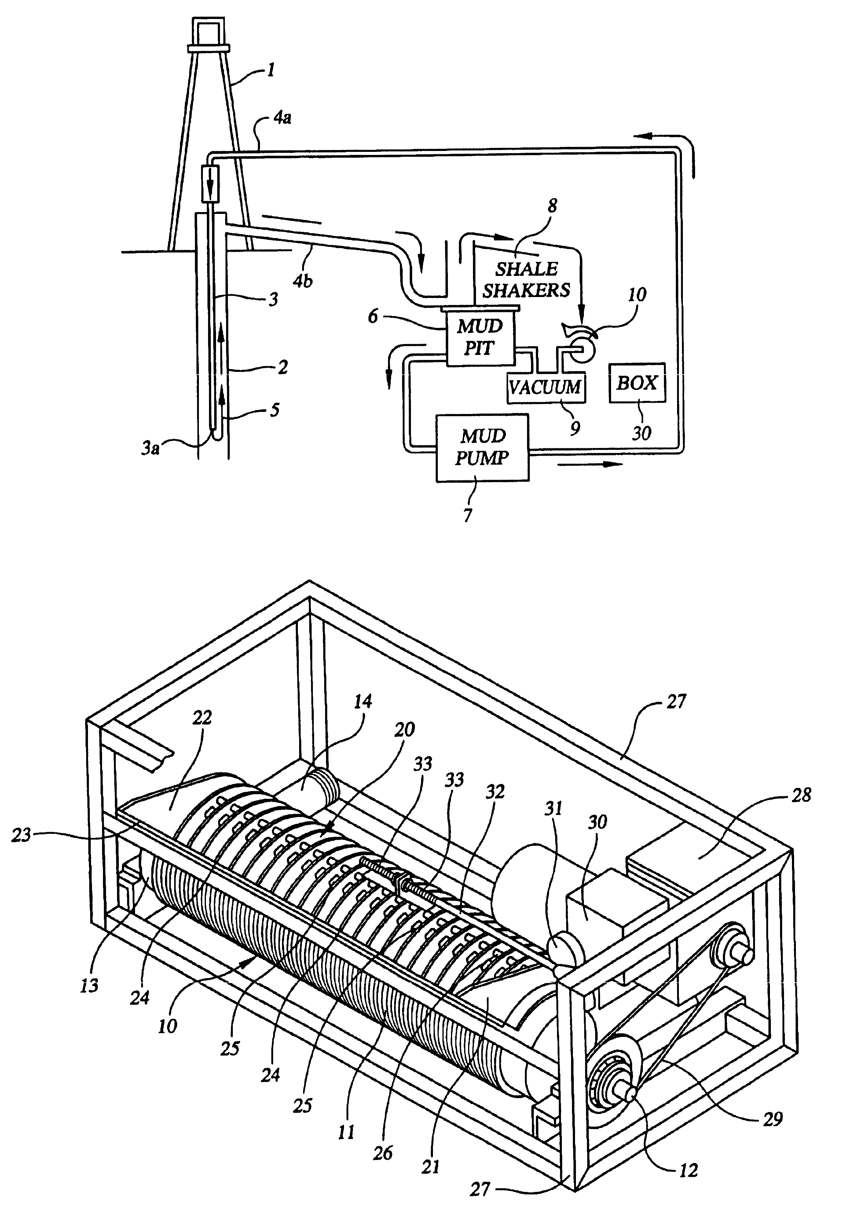
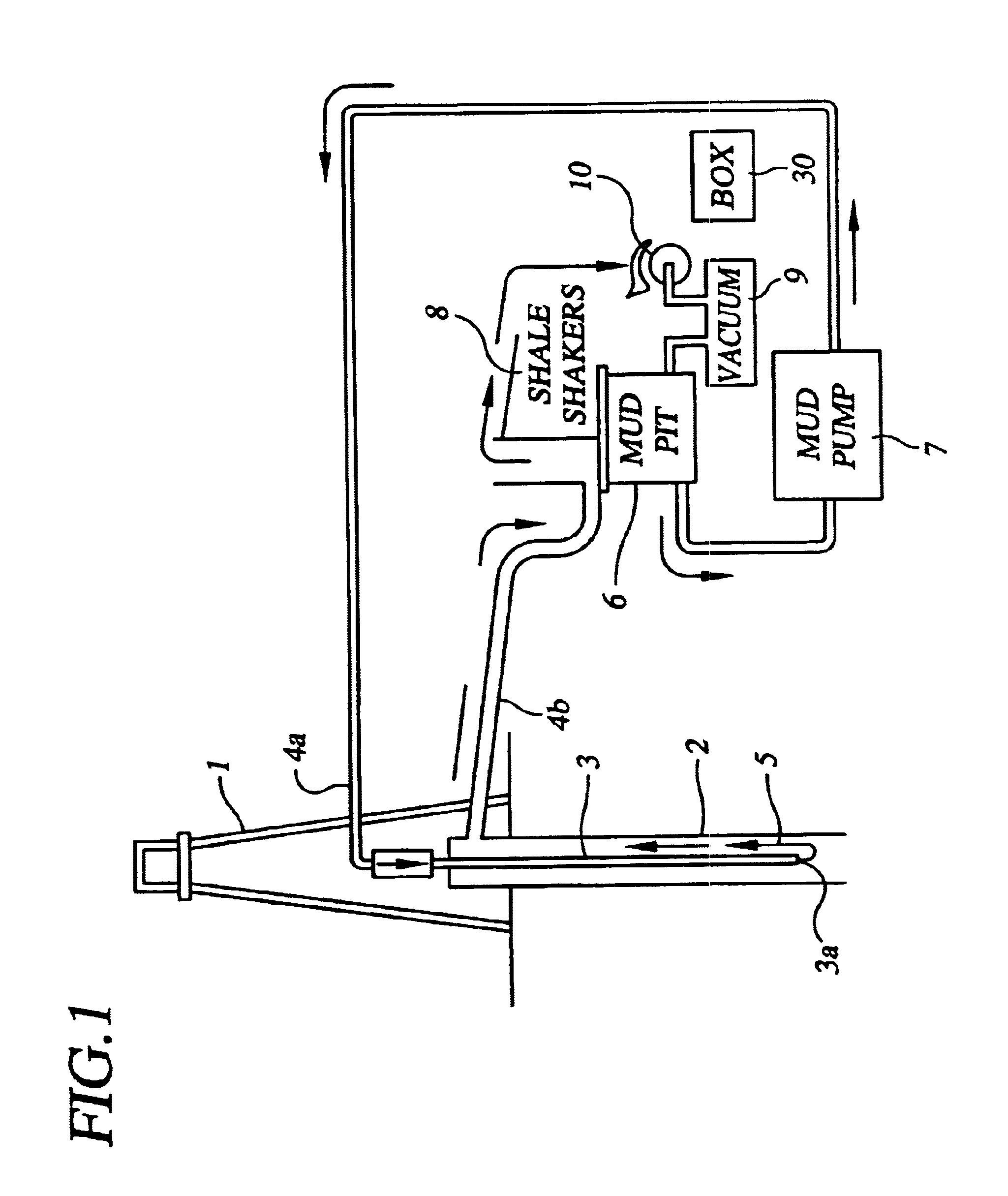
Referring to the drawings, FIG. 1 depicts a schematic overview representation of the mud system of a typical drilling rig. The flow of drilling mud within this mud system in FIG. 1 is in the direction of the arrows.

Still referring to FIG. 1, derrick 1 extends vertically over wellbore 2. Tubular work string 3 is inserted into wellbore 2, and extends from the earth's surface to a desired depth within said wellbore 2. Flow line 4a is connected to said tubular work string 3. Flow line 4b is connected to annular space 5 formed between the outer surface of tubular work string 3 and the inner surface of wellbore 2.

Still referring to FIG. 1, the bulk of the drilling mud for the depicted mud system is in mud pit 6. Mud from said mud pit 6 is circulated through the overall mud system depicted schematically in FIG. 1 via mud pump 7. The mud is pumped into tubular work string 3 through flow line 4a, circulated out the end 3a of tubing 3 up the annulus 5 of wellbore 2, and out of said wellbore a...


PUM

PropertyMeasurementUnit
pressureaaaaaaaaaa
suctionaaaaaaaaaa
residualaaaaaaaaaa

Abstract

A method and apparatus is provided for removing fluids, particularly entrained and / or adherent fluids, from drill cuttings generated during the well drilling process. A generally cylindrical wire-wrapped screen having a bore therethrough rotates about its longitudinal axis. Suction pressure is applied through the inner bore of the cylindrical wire-wrapped screen. As fluid-laden drill cuttings are deposited on the outer surface of the cylindrical wire-wrapped screen, fluids are drawn off of the cuttings and evacuated from the inner bore of the cylindrical wire-wrapped screen. Solid components of the cuttings remain on the outer surface of the cylindrical wire-wrapped screen and eventually roll off the screen. A scraping member is provided to agitate cuttings deposited on the outer surface of the cylindrical wire-wrapped screen.

Description

NONESTATEMENTS AS TO RIGHTS TO INVENTIONS MADE UNDER FEDERALLY SPONSORED RESEARCH AND DEVELOPMENTNONEINVENTORSOWEN THOMAS RISHERNOLAN JOSEPH FITCHRONALD CHARLES LANDRYMICHAEL DAVID BILLEAUDDAVID JON TILLEY1. Field of the InventionThe present invention relates generally to the treatment of drill cuttings generated during oil and gas well drilling operations. More particularly, the present invention relates to a method and apparatus for the removal of fluids, such as drilling mud, mud additives and contaminants, from drill cuttings. More particularly still, the present invention relates to a method and apparatus for the separation of entrained and / or adherent fluids from drill cuttings, thereby permitting recovery of such fluids as well as efficient disposal of the solid components of said drill cuttings.2. Description of the Related ArtDrilling rigs used for the drilling of oil and gas wells typically include a supportive rig floor positioned over a well, a derrick extending vertical...

Claims


Application Information

Patent Timeline
Patent Type & Authority Patents(United States)
IPC IPC(8): E21B21/00E21B21/06
CPCE21B21/065
Inventor RISHER, OWEN THOMASFITCH, NOLAN JOSEPHBILLEAUD, MICHAEL DAVIDTILLEY, DAVID JONLANDRY, RONALD CHARLES
Owner HALLIBURTON ENERGY SERVICES INC
Why Eureka
Try Eureka