Fixed-rate block-based image compression with inferred pixel values

a fixed-rate block and image compression technology, applied in the field of image processing systems, can solve the problems of not being able to randomly access any given symbol, requiring tremendous memory bandwidth and processing power, and each of these methods and systems,

Inactive Publication Date: 2004-01-27
S3 GRAPHICS
View PDF12 Cites 51 Cited by
  • Summary
  • Abstract
  • Description
  • Claims
  • Application Information

AI Technical Summary

Problems solved by technology

To generate such images requires tremendous memory bandwidth and processing power on a graphics subsystem.
Each of these methods and systems, however, have numerous drawbacks.
A problem with Entropy coding is that it does not allow random access to any given symbol.
The part of the compressed data preceding a symbol of interest must be first fetched and decompressed to decode the symbol which takes considerable processing time and resources as well as decreasing memory throughput.
Another problem with existing Entropy methods and systems is that they do not provide any guaranteed compression factor which makes this type of encoding scheme impractical where the memory size is fixed.
One problem with DCT and JPEG-type compressors is that they require usually bigger blocks of pixels, typically 8.times.8 or 16.times.16 pixels, as a minimally accessible unit in order to obtain a reasonable compression factor and quality.
Access to a very small area, or even a single pixel involves fetching a large quantity of compressed data, thus requiring increased processor power and memory bandwidth.
A second problem with DCT and JPEG-type compressors is that the compression factor is variable, therefore requiring a complicated memory management system that, in turn, requires greater processor resources.
A third problem with DCT and JPEG-type compression is that using a large compression factor significantly degrades image quality.
A fourth problem with DCT and JPEG-type compression is that such a decompressor is complex and has a significant associated hardware cost.
Further, the high latency of the decompressor results in a large additional hardware cost for buffering throughout the system to compensate for the latency.
Finally, a fifth problem with DCT and JPEG-type compressors is that it is not clear whether a color keyed image can be compressed with such a method and system.
The BTC / CCC methods quantize each block to just two color levels resulting in significant image degradation.
Thus, such pixel blocks cannot be decoded without fetching additional information that can consume additional memory bandwidth.
Fetching such units, however, decreases system performance because of additional overhead due to memory misalignment.
Another problem with BTC / CCC is that when it is used to compress images that use color keying to indicate transparent pixels, there will be a high degradation of image quality.

Method used


Image

  • Fixed-rate block-based image compression with inferred pixel values
  • Fixed-rate block-based image compression with inferred pixel values
  • Fixed-rate block-based image compression with inferred pixel values

Examples


Embodiment Construction

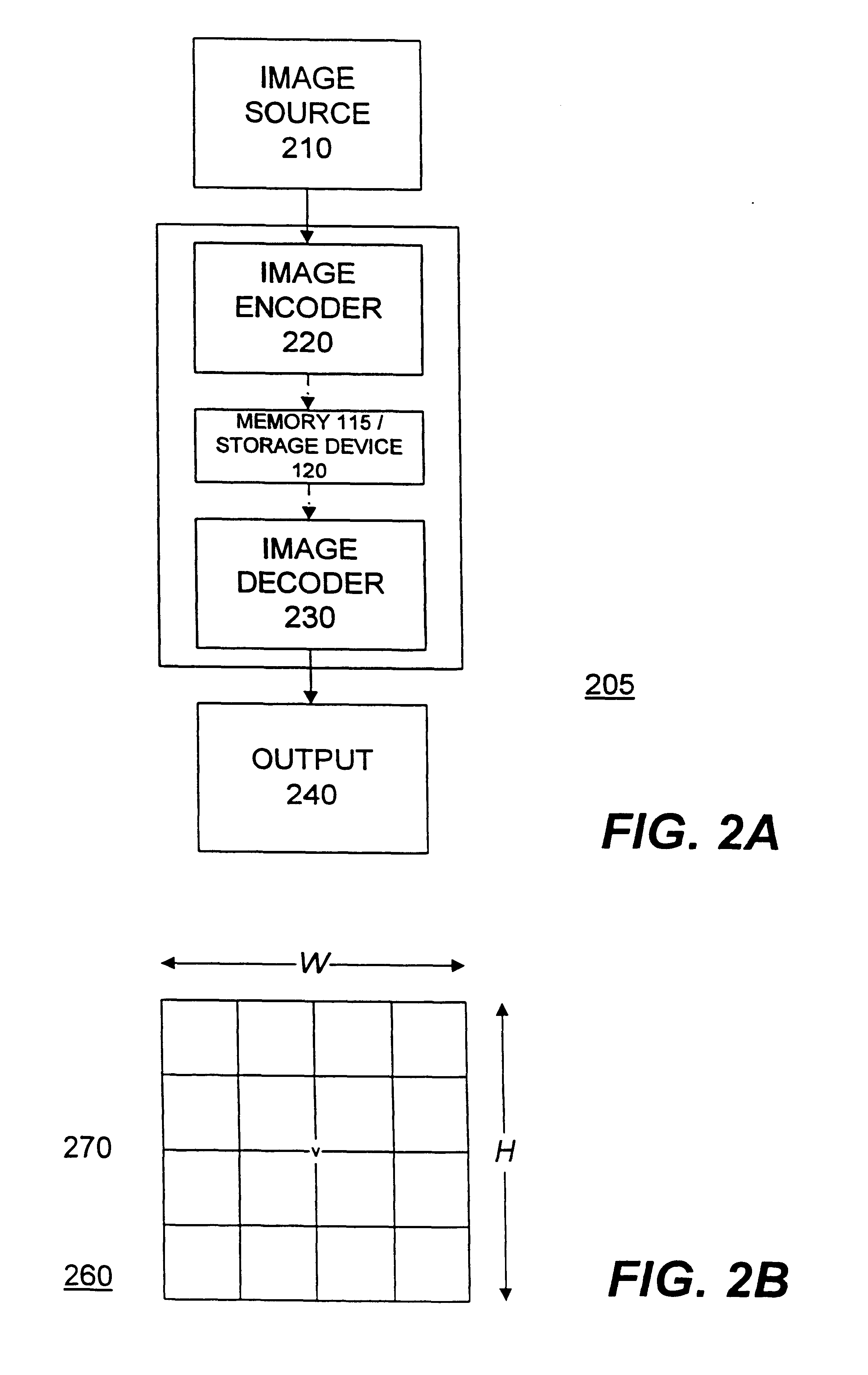
decoded 615 in parallel in multiple block decoders 505a-505m, as described above. The process for decoding the encoded image blocks 390 is further described in FIG. 6B. Each decoded 615 image block is then composed 620 into a data file with the converted 612 header information by the image composer 504. The image composer 504 generates the data file as an output 625 that represents the original image 310.

FIG. 6B is a flow diagram illustrating operation of the block encoder 505 in accordance with the present invention. Once the process is started 630, each encoded image block 390 is received by the block decoder 505 and the block type for each encoded image block 390 is detected 640. Specifically, for a preferred embodiment the first and the second codewords 390a, CW0, CW1, respectively, are received 635 by the block type detector 520 of the block decoder 505. As discussed above, comparing the numerical values of CW0 and CW1 reveals the block type.

In addition, the first five bits of ...


PUM


Abstract

An image processing system includes an image encoder system and a image decoder system that are coupled together. The image encoder system includes a block decomposer and a block encoder that are coupled together. The block encoder includes a color quantizer and a bitmap construction module. The block decomposer breaks an original image into blocks. Each block is then processed by the block encoder. Specifically, the color quantizer selects some number of base points, or codewords, that serve as reference pixel values, such as colors, from which quantized pixel values are derived. The bitmap construction module then maps each pixel colors to one of the derived quantized colors. The codewords and bitmap are output as encoded image blocks. The decoder system includes a block decoder. The block decoder includes a block type detector, one or more decoder units, and an output selector. Using the codewords of the encoded data blocks, the comparator and the decoder units determine the quantized colors for the encoded image block and map each pixel to one of the quantized colors. The output selector outputs the appropriate color, which is ordered in an image composer with the other decoded blocks to output an image representative of the original image. A method for encoding an original image and for decoding the encoded image to generate a representation of the original image is also disclosed.

Description

1. Field of the InventionThe present invention relates to image processing systems, and more specifically, to three-dimensional rendering systems using fixed-rate image compression for textures.2. Description of the Related ArtThe art of generating images, such as realistic or animated graphics on a computer is known. To generate such images requires tremendous memory bandwidth and processing power on a graphics subsystem. To reduce the bandwidth and processing power requirements, various compression methods and systems were developed. These methods and systems included Entropy or lossless encoders, discrete cosine transform or JPEG type compressors, block truncation coding, color cell compression, and others. Each of these methods and systems, however, have numerous drawbacks.Entropy or lossless encoders include Lempel-Ziv encoders and are used for many different purposes. Entropy coding relies on predictability. For data compression using Entropy encoders, a few bits are used to e...

Claims


Application Information

Patent Timeline
Patent Type & Authority Patents(United States)
IPC IPC(8): G06T9/00H03M7/30
CPCG06T9/005H03M7/30H04N19/176H04N19/46H04N19/126H04N19/42H04N19/90G06T9/00
Inventor IOURCHA, KONSTANTINE I.NAYAK, KRISHNA S.HONG, ZHOU
Owner S3 GRAPHICS
Why Eureka
Try Eureka