
Repetitive pattern testing circuit for AC-coupled systems

a pattern testing and parallel ac coupled technology, applied in the field of data communication, can solve the problems of difficult to determine the tolerance of the mark ratio of an entire system using a prbs, and the performance of parallel ac coupled signal paths is not good, and it is impossible to clock all devices at that high ra

Inactive Publication Date: 2004-01-27
CISCO TECH INC
View PDF2 Cites 50 Cited by
  • Summary
  • Abstract
  • Description
  • Claims
  • Application Information

AI Technical Summary

Problems solved by technology

In a data communication network transporting OC-192 signals at 9.953280 Gbps (Giga bits per second), it is impractical to clock all devices at that high rate.
A closed eye pattern corresponds to distortion of the signal waveform due to various errors such as pattern dependency and noise.
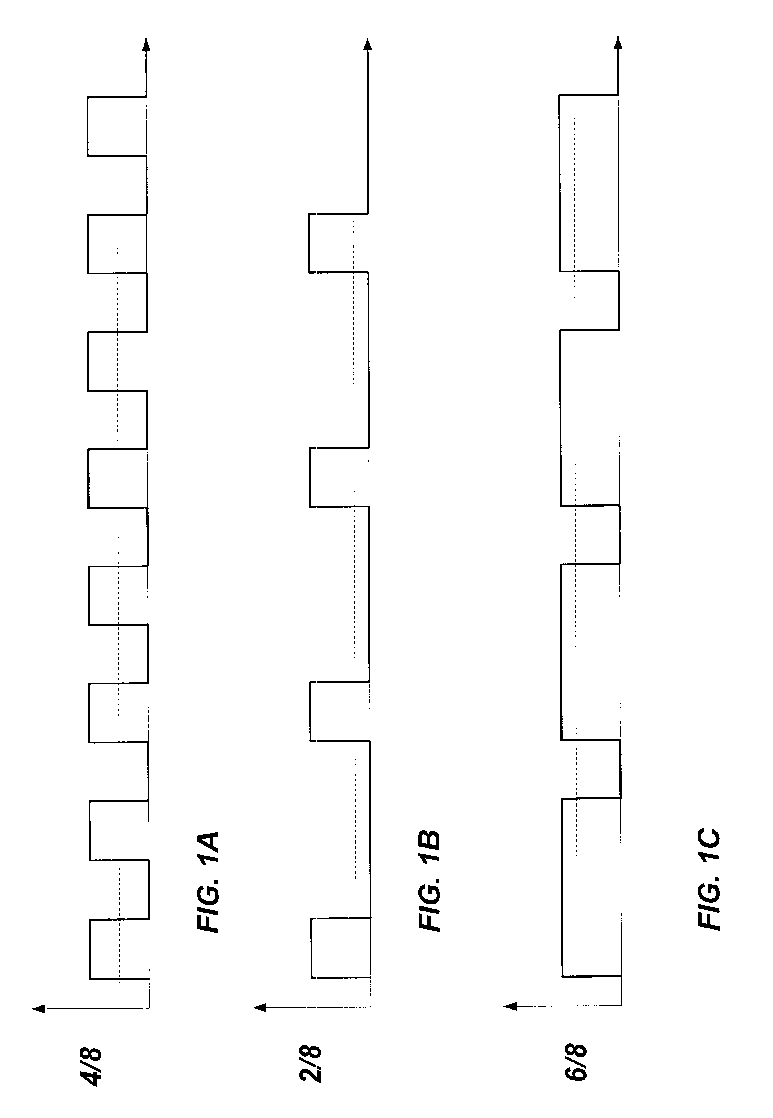
Determining the mark ratio tolerance of an entire system using a PRBS is difficult since a signal path typically consists of multiple components, cabling, and often performs serializing and de-serializing of the data.
Parallel AC coupled signal paths do not perform well under certain test conditions and give erroneous mark ratio tolerance failures.
AC coupling of a parallel path often precludes the use of repetitive test patterns.
DC drift on the capacitors during the mark ratio testing results in bit errors often causing the signal path to effectively shut down and stop functioning.
Previous solutions required the signal path to be tested in pieces, giving only partial results or unreliable overall system mark ratio tolerance results.
This solution is undesirable due to the need to perform measurements in a short amount of time before the capacitors fully charge.
In addition, these large capacitors use a large amount of board space and can be costly.

Method used


Image

  • Repetitive pattern testing circuit for AC-coupled systems
  • Repetitive pattern testing circuit for AC-coupled systems
  • Repetitive pattern testing circuit for AC-coupled systems

Examples


Embodiment Construction

)

The following is intended to provide a detailed description of an example of the invention and should not be taken to be limiting of the invention itself. Rather, any number of variations may fall within the scope of the invention that is defined in the claims following the description.

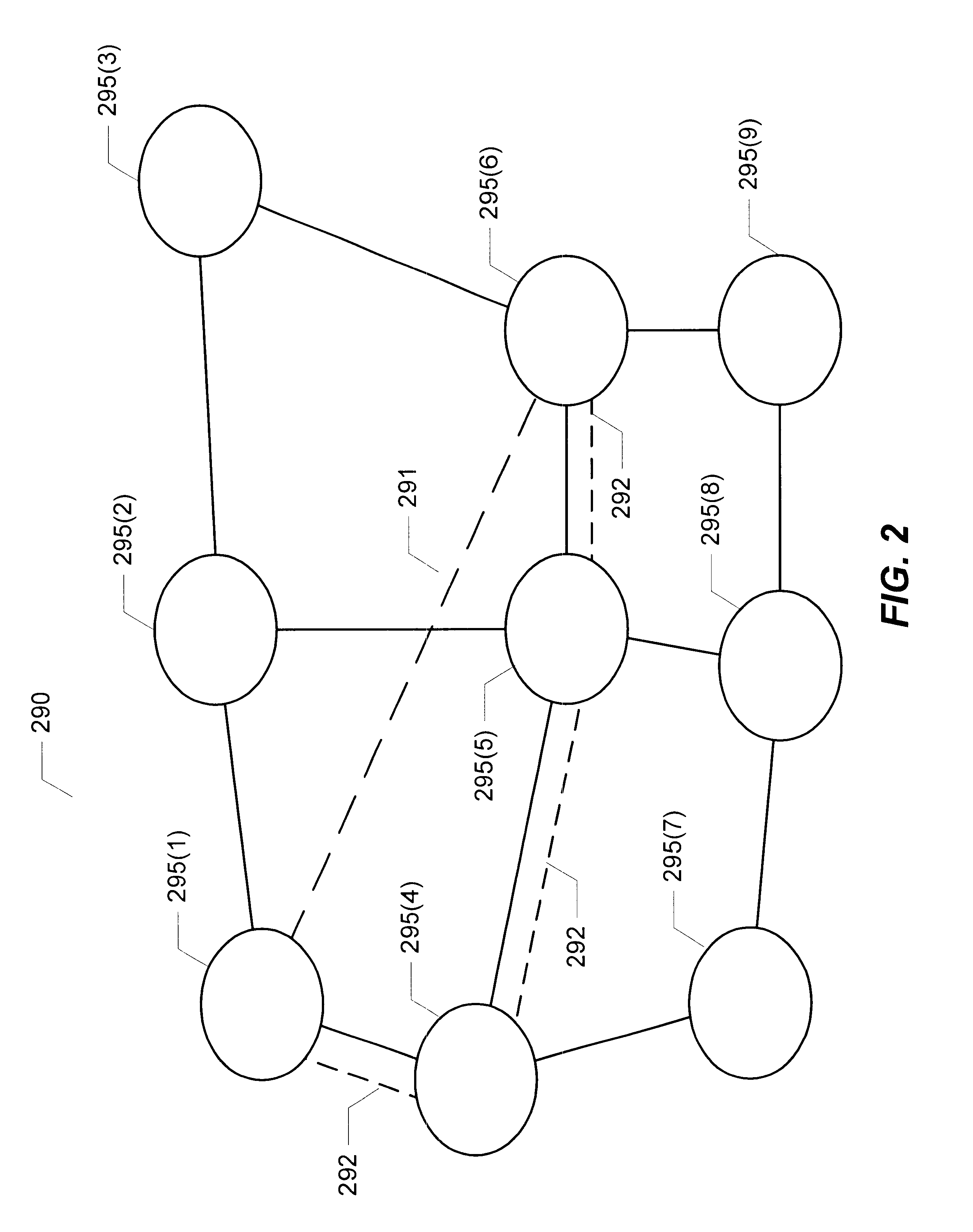
FIG. 2 illustrates a network environment in which embodiments of the present invention may be practiced. Network 290 includes a number of nodes, network nodes 295(1)-(N). One or more of network nodes 295(1)-(N) can be a router such as router 300, described in FIG. 3, or any other type of telecommunication hub such as a repeater. Network 290, for example, can support the automatic provisioning, testing, restoration, and termination of virtual paths (exemplified by a virtual path 291) over a physical path (exemplified by a physical path 292) from one of network nodes 295(1)-(N) to another of network nodes 295(1)-(N). Physical path 292 may utilize fiber-optic cables, for example. While copper cabling ma...


PUM


Abstract

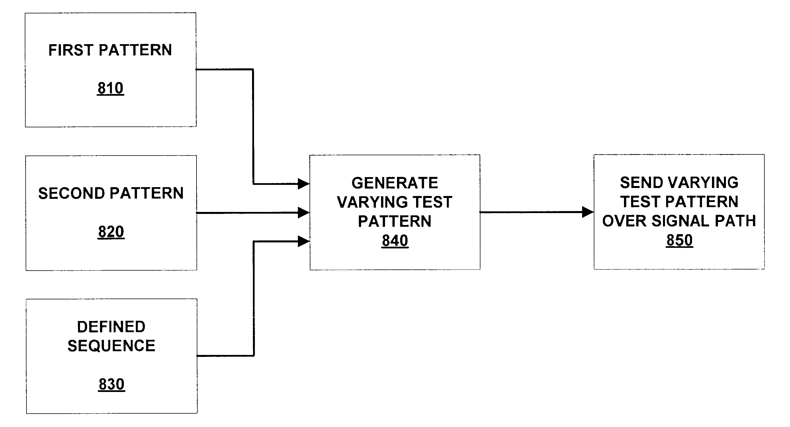
A method for testing a signal path for mark ratio tolerance includes generating a varying test pattern by selecting between a first pattern and a second pattern according to a defined sequence; and sending the varying test pattern over the signal path. An apparatus disposed in a communication system includes a selection circuit for generating a varying test pattern to send over the signal path, the selection circuit generating the varying test pattern by selecting between a first pattern and a second pattern according to a select sequence signal, and a sequencer coupled to the selection circuit, the sequencer providing the select sequence signal to the selection circuit, the sequencer generating the select sequence signal according to a mode value. The mark ratio tolerance of a system can be tested, varying the data density of one portion of the signal path while maintaining a constant data density on another portion of the signal path.

Description

1. Field of the InventionThe present invention relates generally to data communications, and more particularly to performance testing of high speed data links.2. Description of the Related ArtA data communications network is the interconnection of two or more communicating entities (i.e., data sources and / or sinks) over one or more data links. A data communications network allows communication between multiple communicating entities over one or more data communications links. High bandwidth applications supported by these networks include streaming video, streaming audio, and large aggregations of voice traffic. In the future, the demands for high bandwidth communications are certain to increase. To meet such demands, an increasingly popular alternative is the use of lightwave communications carried over fiber optic cables. The use of lightwave communications provides several benefits, including high bandwidth, ease of installation, and capacity for future growth.The synchronous opt...

Claims


Application Information

Patent Timeline
IPC IPC(8): H04L1/24H04L1/08
CPCH04L1/24H04L1/08
Inventor THEODORAS, II, JAMES T.THURSTON, ANDREW J.CHAPLIN, DANIEL L.
Owner CISCO TECH INC
Learn More