Wheel support bearing assembly

a technology of bearings and bearings, which is applied in the direction of mechanical equipment, instruments, transportation and packaging, etc., can solve the problems of interference with the magnetic sensor, the gap cannot be set to a very small size, and the failure to detect the number of rotations of the wheel properly

Inactive Publication Date: 2004-02-17
NTN CORP
View PDF2 Cites 53 Cited by
  • Summary
  • Abstract
  • Description
  • Claims
  • Application Information

AI Technical Summary

Benefits of technology

According to the first aspect of the present invention, since the protective cover is used and positioned exteriorly of the multi-pole magnet forming a part of the magnetic encoder so that the number of revolution can be detected through the protective cover, any possible "biting" of foreign matter in between the magnetic sensor for the detection of the number of revolutions and the multi-pole magnet can be prevented by the presence of the protective cover. Also, even if the foreign matter is caught in between the protective cover and the magnetic sensor, the foreign matter does not directly contact the multi-pole magnet and, therefore, the multi-pole magnet is hardly damaged. Also, since the protective cover is positioned adjacent the multi-pole magnet forming the part of the magnetic encoder with the predetermined air gap intervening therebetween, rotation of the multi-pole magnet will not be disturbed by the protective cover. Yet, since the protective cover is made of the non-magnetic material, detection of the magnetic encoder by the magnetic sensor will not be disturbed undesirably.
Preferably, the protective cover may have an inner peripheral edge formed with a reinforcement rib. The provision of the reinforcement rib at the inner peripheral edge of the protective cover is effective to avoid any possible deformation of the inner peripheral edge of the protective cover during crimping of the outer peripheral edge portion thereof and, therefore, there is no possibility that the bondability of the protective cover to the multi-pole magnet may be reduced as a result of a possible deformation. In general the gap between the multi-pole magnet and the magnetic sensor confronting the multi-pole magnet is advantageously set to a very small gap in order to increase the magnetic characteristic by reducing the magnetic gap. For this reason, if the bondability of the protective cover to the multi-pole magnet is insufficient, interference with the magnetic sensor will occur and the gap cannot be set to a very small size. The problem associated with this interference resulting from the insufficient bondability can be eliminated by the presence of the reinforcement rib at the inner peripheral edge of the protective cover.

Problems solved by technology

With the known wheel support bearing assembly of the structure discussed above, it has been found that in the event of ingress of foreign matter such as, for example, stones or rocks into a working gap delimited between the multi-pole magnet 111 and the magnetic sensor 110, the multi-pole magnet 111 and, hence, the magnetic encoder 106 may be impaired, resulting in failure to detect the number of revolutions of the wheel properly.
For this reason, if the bondability of the protective cover to the multi-pole magnet is insufficient, interference with the magnetic sensor will occur and the gap cannot be set to a very small size.
However, if the thickness is too small, the protective cover will lack a sufficient strength and the bondability between the multi-pole magnet and the protective cover will be lost as a result of deformation taking place during the crimping of the peripheral edge portion of the protective cover.
If the thickness of the protective cover is not greater than 0.1 mm, there is the possibility of the protective cover being deformed as discussed above, but if it exceeds 1.0 mm, the magnetic gap will increase excessively.
However, if the hardness exceeds Hv 200, there is the possibility that the protective cover may be deformed during crimping of the outer peripheral edge portion thereof.

Method used


Image

  • Wheel support bearing assembly
  • Wheel support bearing assembly
  • Wheel support bearing assembly

Examples


first embodiment

[First Embodiment]

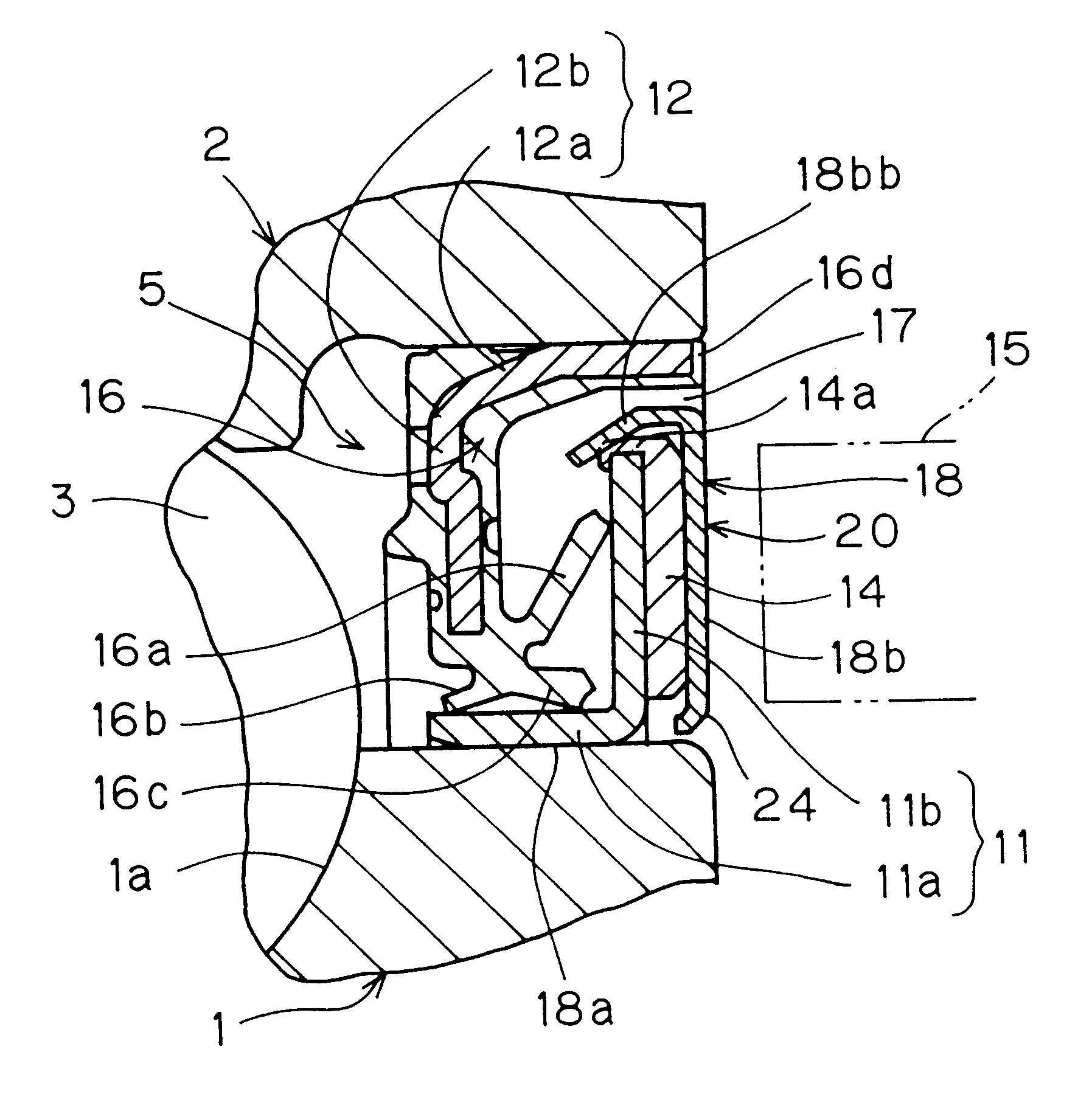
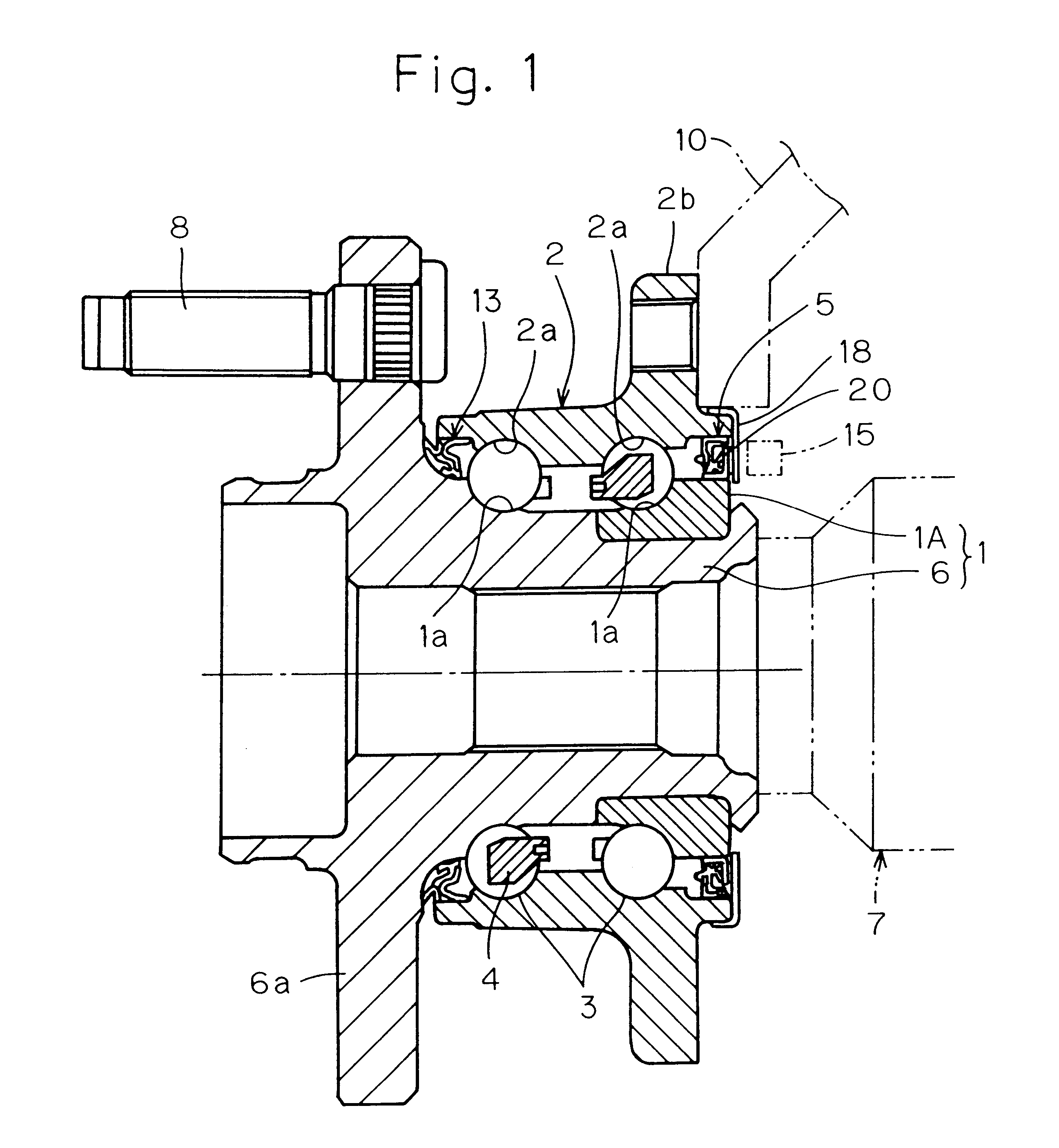
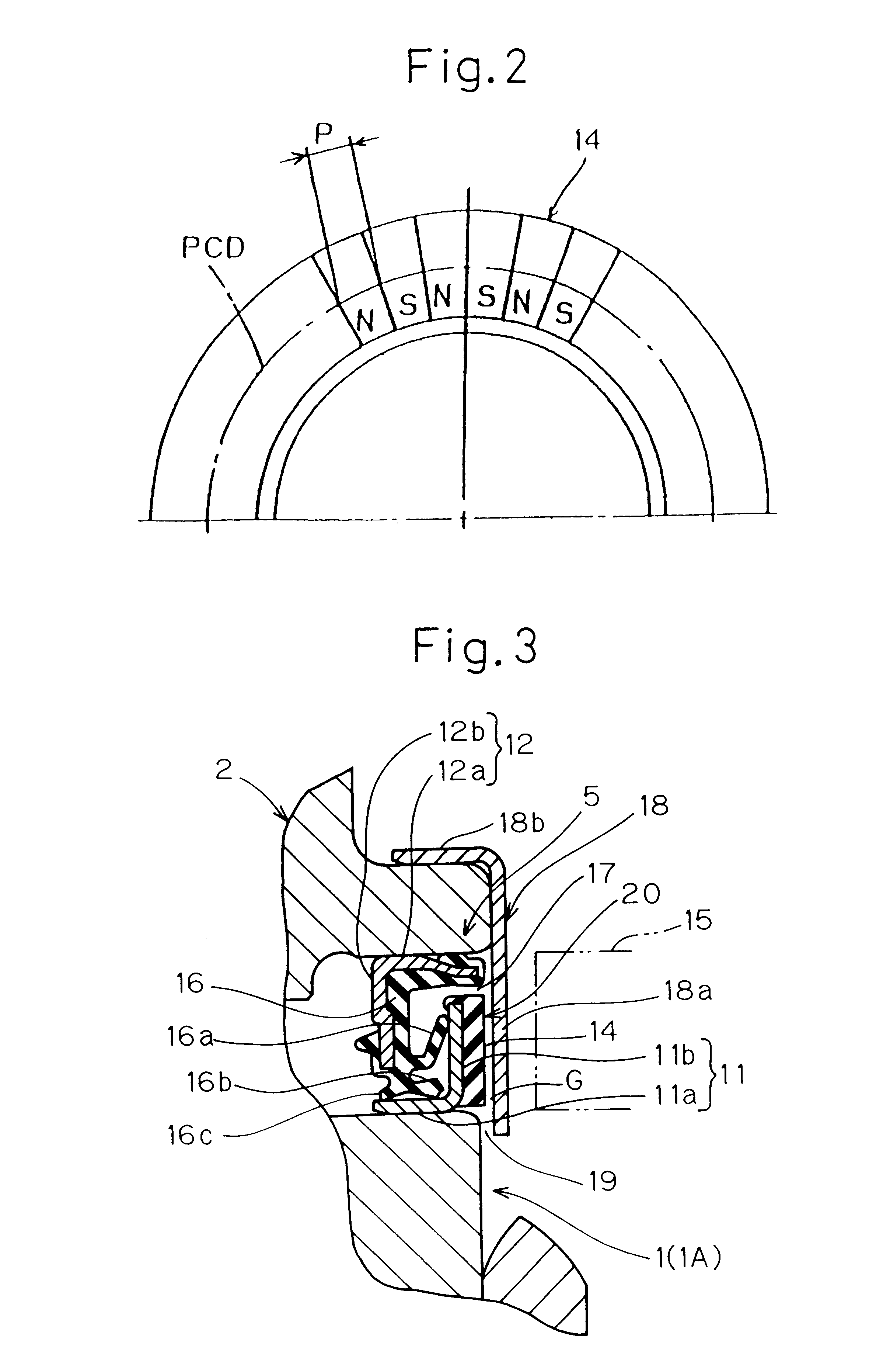
In the first place, with particular reference to FIGS. 1 to 3 showing a first preferred embodiment of the present invention, the wheel support bearing assembly shown therein will be described in the context of that used for supporting a drive wheel, in which the magnetic encoder concurrently serve as a slinger.

As shown in FIG. 1, the wheel support bearing assembly includes generally cylindrical inner and outer members 1 and 2 one positioned radially inside the other to define an annular bearing space, a plurality of, for example, two, rows of rolling elements 3 interposed between the inner and outer members 1 and 2 and rollingly movably positioned within the annular bearing space, and annular sealing devices 5 and 13 accommodated within and positioned adjacent opposite ends of the annular space, respectively, to seal the annular bearing space. It is to be noted that one of the sealing devices, that is, the sealing device 5 is provided with a magnetic encoder 20 as ...

second embodiment

[Second Embodiment]

The wheel support bearing assembly according to a second preferred embodiment of the present invention will now be described with reference to FIGS. 9 and 10. As is the case with the first embodiment of the present invention, the wheel support bearing assembly according to this embodiment is assumed as used for the support of the drive wheel and is thus similar in structure and function to that according to the first embodiment, except for the difference residing in that while the wheel support bearing assembly shown in FIGS. 1 to 3 employs the hub assembly of the structure including the barrel hub 6 with one of the inner race integrated therewith and the other inner race 1A, the wheel support bearing assembly reffered to as a first generation and shown in FIGS. 9 and 10 employs a three-component hub assembly of a structure including a barrel hub 6 and split-type inner races 1A and 1B. Other structural features of the wheel support bearing assembly shown in FIGS. ...

third embodiment

[Third Embodiment]

The wheel support bearing assembly according to a third preferred embodiment of the present invention will now be described with reference to FIG. 14. The wheel support bearing assembly according to this third embodiment is featured in that the protective cover 18 is fitted to the inner member 11 and that the multi-pole magnet 14 of the magnetic encoder 20 is secured to an axially inner surface of the upright wall 18b of the protective cover 18 by means of a bonding technique. Where the multi-pole magnet 14 is in the form of the rubber magnet, it may be secured by vulcanization to the upright wall 18b of the protective cover 18. A gap may or may not be formed between the radial wall 11b of the first sealing plate 11 and the multi-pole magnet 14. In such case, the multi-pole magnet 14 and the protective cover 18 altogether form the magnetic encoder 20. It is to be noted that in the embodiment shown in FIG. 14, the radial outer edge portion of the upright wall 18b of...


PUM


Abstract

A wheel support bearing assembly includes inner and outer members (1 and 2) and at least one row of rolling elements (3) operatively interposed between the inner and outer members (1 and 2) and an annular sealing device (5) sealing an open end of an annular space defined between the inner and outer members (1 and 2). The sealing device (5) includes first and second annular sealing plates (11 and 12) fitted to different members out of the inner and outer members (1 and 2). Each of the first and second sealing plates (11 and 12) includes a generally cylindrical wall (11a or 12a) and a radial wall (11b or 12b) assembled together to represent a generally L-shaped section. The first sealing plate (11) is fitted to one of the inner and outer members (1 and 2) that serves as a rotating member. An elastic member (14) mixed with a powdered magnetic material is bonded by vulcanization to the radial wall (11b) of the first sealing plate (11). A protective cover (18) made of a non-magnetic material is positioned on one side adjacent an exterior of the multi-pole magnet (14) with a predetermined air gap left therebetween that the number of revolution can be detected through the protective cover (18).

Description

1. Field of the InventionThe present invention generally relates to a wheel support bearing assembly for an automotive vehicle or the like and, more particularly, to the wheel support bearing assembly integrated with a magnetic encoder for detection of the number of revolution of a wheel.2. Description of the Prior ArtAs shown in FIG. 23, the wheel support bearing assembly is well known, which includes generally cylindrical inner and outer members 101 and 102 positioned one radially inside the other with an annular space defined therebetween, dual rows of rolling elements 103 interposed between the inner and outer members 101 and 102 and rollingly movably positioned within the annular space, an annular sealing device 105 accommodated within and positioned at one of opposite ends of the annular space, and an annular magnetic encoder 106 integrated together with the sealing device 105. This known wheel support bearing assembly is disclosed in, for example, the Japanese Laid-open Paten...

Claims


Application Information

Patent Timeline
Patent Type & Authority Patents(United States)
IPC IPC(8): B60B27/00F16C33/78F16C33/76G01P3/44G01P3/42F16C19/18F16C19/52F16C32/00F16C33/72F16C41/04F16J15/32G01P3/48G01P3/54
CPCB60B27/00F16C33/723F16C41/007F16J15/326G01P3/443F16C33/7883F16C33/805F16C2326/02F16C19/184F16C19/186
Inventor OHTSUKI, HISASHINORIMATSU, TAKAYUKI
Owner NTN CORP
Why Eureka
Try Eureka