
Disc recording apparatus, method for replacing sector on recording disc, and recording disc

Inactive Publication Date: 2004-02-24
FUJITSU LTD
View PDF9 Cites 62 Cited by
  • Summary
  • Abstract
  • Description
  • Claims
  • Application Information

AI Technical Summary

Benefits of technology

It is therefore an object of the present invention to provide a disc recording apparatus, a method for replacing sector on a recording disc and the recording disc, capable of reducing the access time without spending as much time when data writing is not successful.
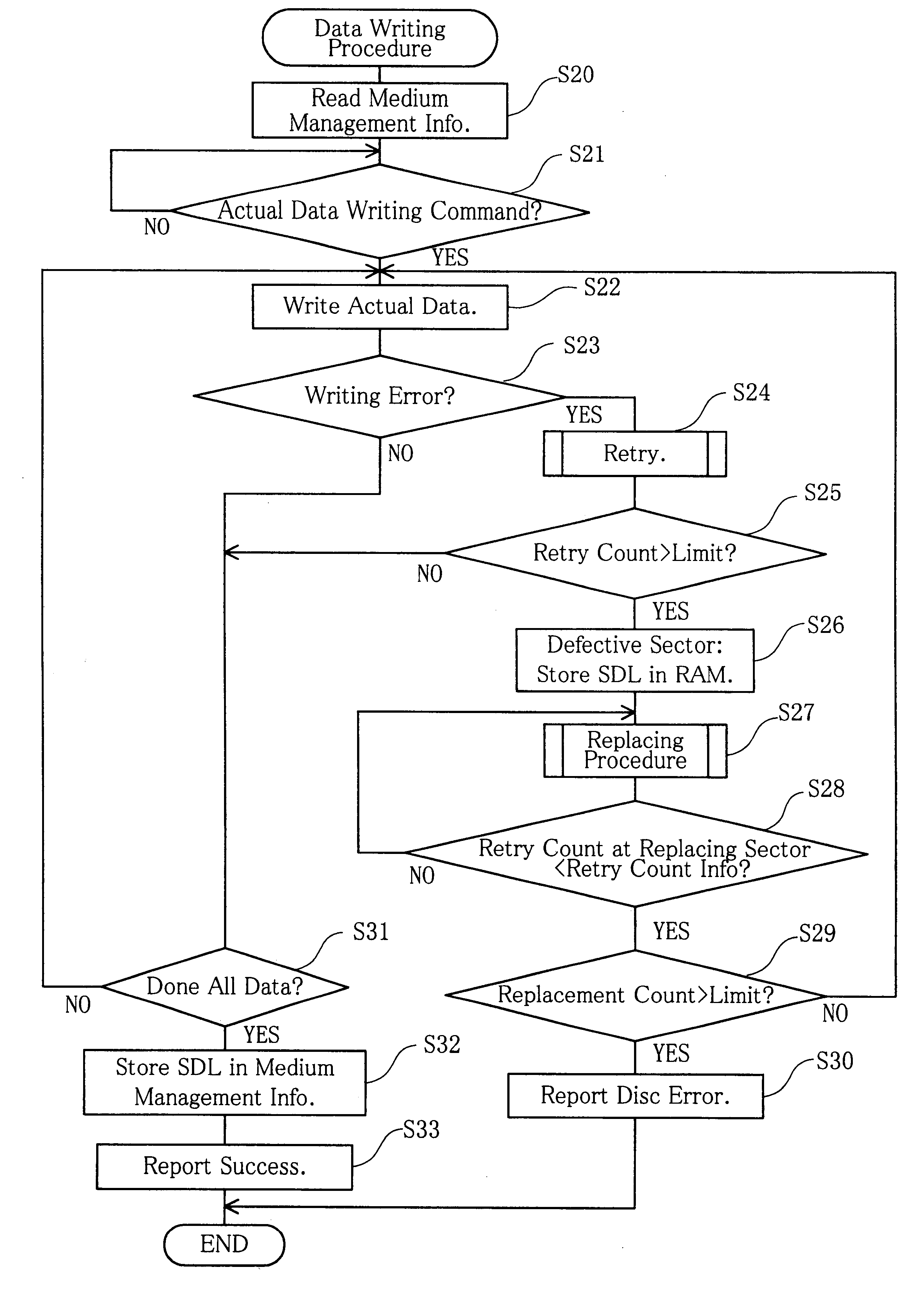
In other words, the restored sectors, i.e. sectors which are made usable through the retry are given low priority for serving as a replacement sector because of a high risk of failure in data writing. Thus, it is possible to select a sector to which the data writing will be successful at the first attempt, without requiring any retries for example. Therefore, even if there is a failure in data writing onto a sector, there is a high probability of success in the replacement sector, and the number of retries and the time necessary for the retry procedures are held minimum, making possible to decrease the access time.

Problems solved by technology

This has increased probability of error occurrence when writing data on the magneto-optical disc.
This means that a long time is spent in vain for retries, resulting in prolonged access time.
However, there is no guarantee that the writing will be successfully completed in the replacing sector.
Sometimes, the replacing sector has a higher error probability than the replaced sector which was found defective.
As understood, execution of the re-replacement procedure means that the replacement procedure is repeated twice or even more times in order to write actual data onto one sector, that a huge number of retries must be made for the writing of actual data, and as a result, that a long time is needed for the writing of actual data including the time spent for the replacement procedures.
This creates a delay in response to the "write" command from the personal computer C10, leading to a "timeout" error in the personal computer C10.

Method used


Image

  • Disc recording apparatus, method for replacing sector on recording disc, and recording disc
  • Disc recording apparatus, method for replacing sector on recording disc, and recording disc
  • Disc recording apparatus, method for replacing sector on recording disc, and recording disc

Examples


first embodiment

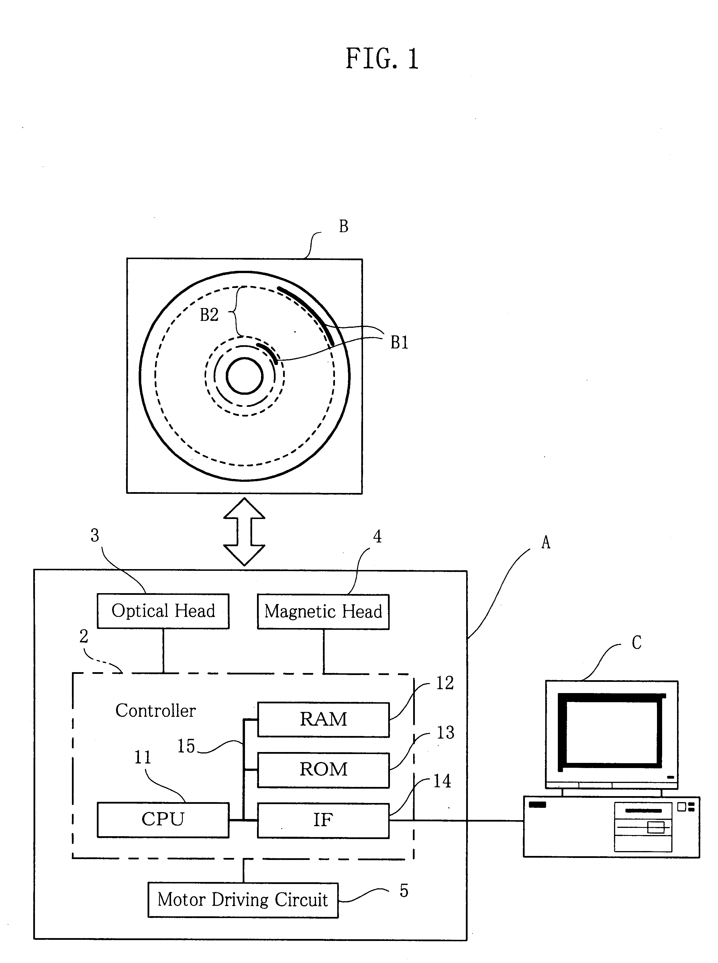
Hereinafter, the present invention will be described with reference to FIG. 1 through FIG. 4.

As shown in FIG. 1, the first embodiment of the present invention uses, a recorder / player A as the disc recording apparatus, a magneto-optical disc B as the recording disc and a personal computer C as a host which directs reading and writing of data. As a matter of fact, the recorder / player A not only can record data and information onto the magneto-optical disc B but also can read the recorded data and information therefrom. The personal computer C, operating on the basis of an OS (Operating System) which provides file managing capabilities, does not have any new essential characteristics, and therefore will not be described or illustrated in specific details.

First, description will be made for the magneto-optical disc B. The magneto-optical disc B is provided by e.g. MO discs, of different capacities such as 230 MB, 540 MB, 640 MB, and 1.3 GB. The magneto-optical disc B has a multiple of t...

second embodiment

Next, a second embodiment will be described with reference to FIG. 1, FIG. 5 and FIG. 6. Note that flowcharts given in FIG. 5 and FIG. 6 contain same steps as in FIG. 3 or FIG. 4. These steps will be identified by the same step numbers and not be described again.

According to the second embodiment, as shown in the flowchart given in FIG. 5 and continuing to FIG. 6, the formatting procedure is followed by the actual-data writing procedure. This covers a case, for example, in which a personal computer C sends a physical formatting request and then an actual-data writing request right after the formatting is completed, without unloading a magneto-optical disc B.

A major difference from the first embodiment is that after a PDL is stored in the medium management information B1 of the magneto-optical disc B in step S18, the CPU 11 makes the RAM 12 keep the retry count information (S40), i.e. a retry count value for each restored sector which is already stored in the RAM 12, and does not cop...

third embodiment

Next, a third embodiment will be described with reference to FIG. 1, FIG. 7 and FIG. 8. Note that flowchart given in FIG. 7 contains the same steps as in FIG. 4. These steps will be identified by the same step numbers and not be described again.

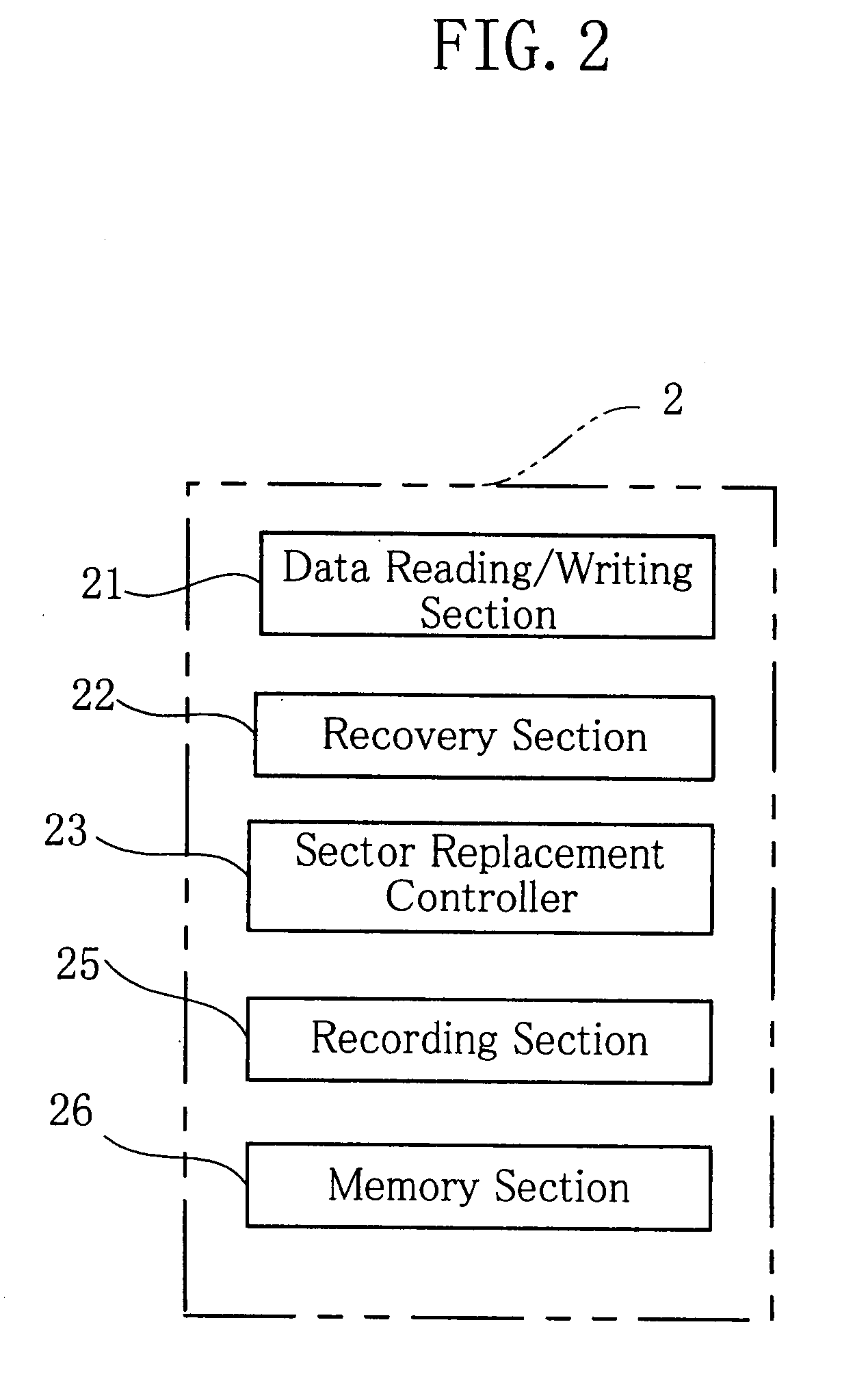
According to the third embodiment, writing of actual data is accomplished through an operation which is slightly different from the operation in the first embodiment. In order to achieve the new operation, as shown in FIG. 7, the controller 2 further includes a defect register 24.

The defect register 24 is realized by the CPU 11, and performs as follows: During the steps of detecting a defective sector and then finding a replacement sector, if a candidate sector is found to have a retry count value greater than a retry count value recorded for the defective sector, the candidate sector is also registered in the RAM 12 as a defective sector.

Specifically, as shown in FIG. 8, when step S28 determines that the candidate replacement sector will req...


PUM


Abstract

A disc recording apparatus (A) for writing data onto a sector providing a recording area (B2) on a magneto-optical disc (B) performs a retry upon failure in the writing until a predetermined number of retries is reached, treats the sector as a defective sector upon failure in the last retry of the predetermined number of retries, and writes the data onto another sector. During a physical formatting, A CPU (11) records in medium management information (B1) on the recording disc (B) a retry count as retry count information for each of recovered sectors recovered from the failure through success in the writing of data during the retry. When actual data is written onto the physically formatted magneto-optical disc (B), and upon detection of a defective sector failed in the writing of the actual data, the CPU (11) selects a replacement sector for the defective sector. The replacement sector has a retry count stored as the retry count information smaller than that of the defective sector.

Description

TECHNICAL FIELDThe present invention relates to a disc recording apparatus for recording data onto e.g. a magneto-optical disc while detecting defective sectors. The present invention also relates to a method for the apparatus to replace a sector on the recording disc. The present invention further relates to the recording disc.BACKGROUND ARTDue to increased capacity, magneto-optical discs in recent years have an increasingly narrow track pitch. This has increased probability of error occurrence when writing data on the magneto-optical disc. At the time of data writing error, a retry is made as many times as predetermined. If the data writing is not successful within the predetermined number of retries, a decision is made finally that the writing has failed. A recent tendency is that the number of retries (retry count) is also increasing. This means that a long time is spent in vain for retries, resulting in prolonged access time. Consequently, there is a need for a technique to red...

Claims


Application Information

Patent Timeline
IPC IPC(8): G11B20/12G11B20/10G11B20/18G11B7/00
CPCG11B20/10527G11B20/1217G11B20/1251G11B20/1883G11B7/00G11B2020/183G11B2220/20G11B2220/2525
Inventor OZAKI, KOJI
Owner FUJITSU LTD
Learn More