
Method for software controllable dynamically lockable cache line replacement system

a dynamic lock and cache technology, applied in computing, instruments, electric digital data processing, etc., can solve the problems of increasing the difference between instruction execution time and instruction latency, affecting the operation speed of the computer processor, and still existing a disparity between the operation frequency and the access time of the computer processor for data

Inactive Publication Date: 2006-02-16
GOOGLE LLC
View PDF9 Cites 47 Cited by
  • Summary
  • Abstract
  • Description
  • Claims
  • Application Information

AI Technical Summary

Benefits of technology

[0002] Computer processors use cache memories to reduce the access time for instructions as well as other data. Computer systems having a main memory containing all necessary instructions for executing an application suffer from execution delays because of the time needed to recover a necessary instruction from the mass memory. Accordingly, a cache memory is provided which permits the processor during a pre-fetch process to move instructions from the main memory to the cache memory where they may later be accessed when needed.
[0003] Even though cache memories speed up the access time for retrieving instructions, there still exists a disparity between the computer processor operational frequency and the access time for data to be stored in the cache. Cache designs, known as an L2 cache and a sum address decode L1 cache, which allow simultaneous access to a translation buffer (TLB) and an instruction or data cache, have been developed to reduce the void or idle time in processor execution due to the latency for a line fetch.
[0004] The design of cache memories must take into account the high clock speeds for the processors, which tend to increase the difference between instruction latency and instruction execution time, and are limited by the physical size of the memory. As an approach for maximizing cache memory performance while increasing the clock frequency, a 4-way set-associate cache may be optimum for certain applications. A 4- or 8-way set-associated cache has shown significant performance benefits without a complex output multiplexer circuit, and without a complex array for identifying which lines within a cache may be replaced. By set-associative, it is understood by those skilled in the art that a plurality of memories are addressed at the same time by a common address portion. The plurality of memories all map to a single cache line, and one of the cache lines from the set-associative memory is selected by a multiplexer using tag information accompanying the address. The set-associative cache stores only a portion of the instructions of a main memory which contains all the instructions needed for execution by the processor. During a pre-fetch operation (or any fetch operation), the processor must select certain lines for replacement so that new instructions are available in the cache for a subsequent execution cycle. Various algorithms have been implemented to select which of the lines are to be replaced. A commonly used replacement algorithm selects the least recently used (LRU) lines for replacement. In most cases, the replacement controller keeps track of cache line usages and replacement begins by selecting the cache line which has been least recently used for replacement.

Problems solved by technology

Computer systems having a main memory containing all necessary instructions for executing an application suffer from execution delays because of the time needed to recover a necessary instruction from the mass memory.
Even though cache memories speed up the access time for retrieving instructions, there still exists a disparity between the computer processor operational frequency and the access time for data to be stored in the cache.
The design of cache memories must take into account the high clock speeds for the processors, which tend to increase the difference between instruction latency and instruction execution time, and are limited by the physical size of the memory.
However, even when employing this line replacement algorithm, there are cache lines such as processor instructions which are known to be frequently used and needed in the future, even though they may meet the replacement requirements of the LRU algorithm.

Method used


Image

  • Method for software controllable dynamically lockable cache line replacement system
  • Method for software controllable dynamically lockable cache line replacement system
  • Method for software controllable dynamically lockable cache line replacement system

Examples


Embodiment Construction

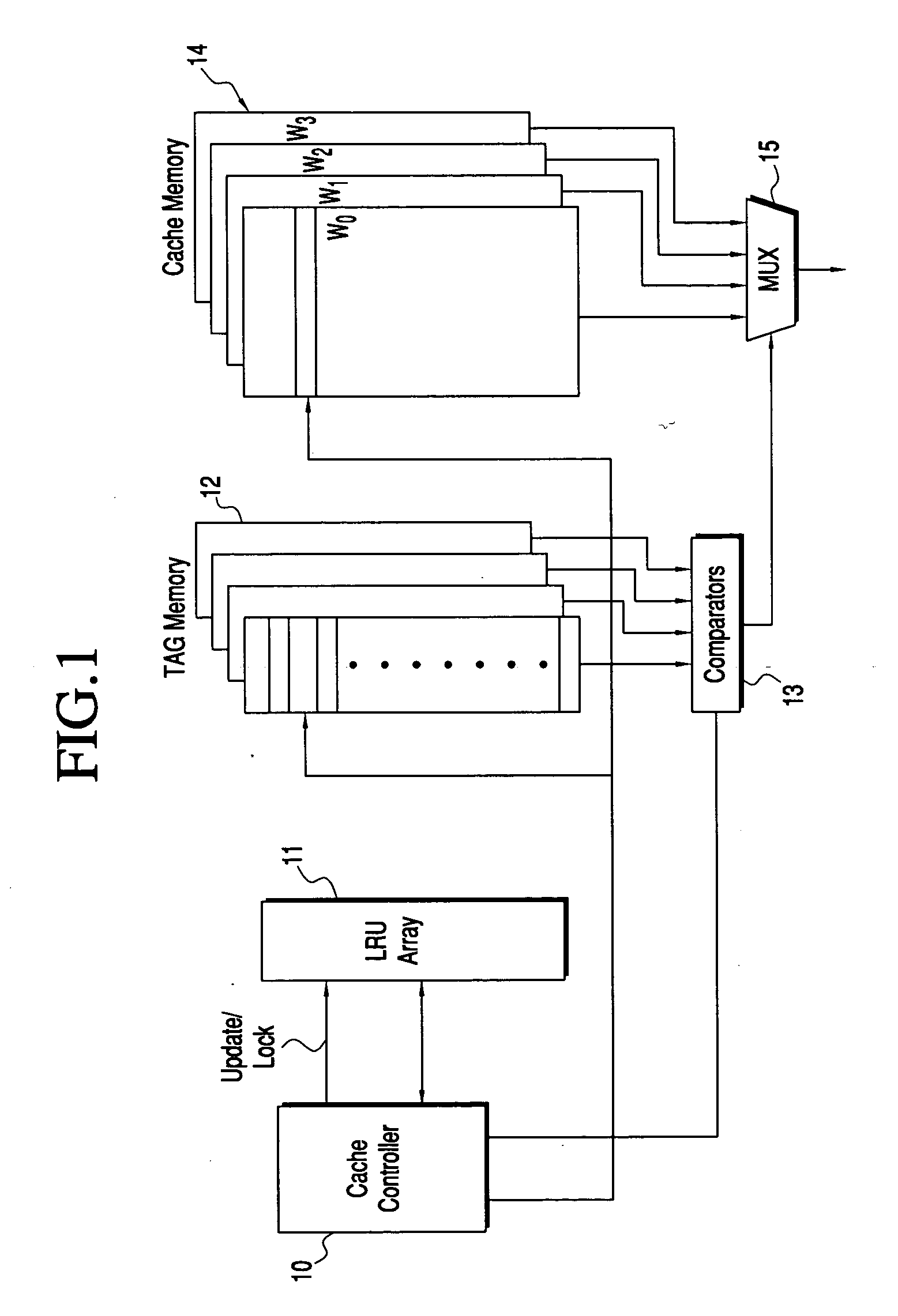
[0012] Referring now to FIG. 1, there is shown a 4-way set-associative cache 14 under control of a cache controller 10. The set-associative cache includes ways W0, W1, W2 and W3, each set storing a line of data, such as instructions for execution by a processor. Each of the ways can include 256 lines of data, and each cache line produced from the set-associative cache 14 has a common address element so that four cache lines are addressed at once to produce a cache line of data from each of the ways W0, W1, W2 and W3. One of these lines of data is selected by multiplexer 15 based on the output from a tag memory array 12.

[0013] The lower order portion of the address provided by the processor addresses each of four tag arrays in the tag memory 12 as well as the ways of the cache memory. The higher order portion of the address is presented to a comparator 13, and when the output of a tag array agrees with the higher order portion of the address, then a cache selection signal is produce...


PUM


Abstract

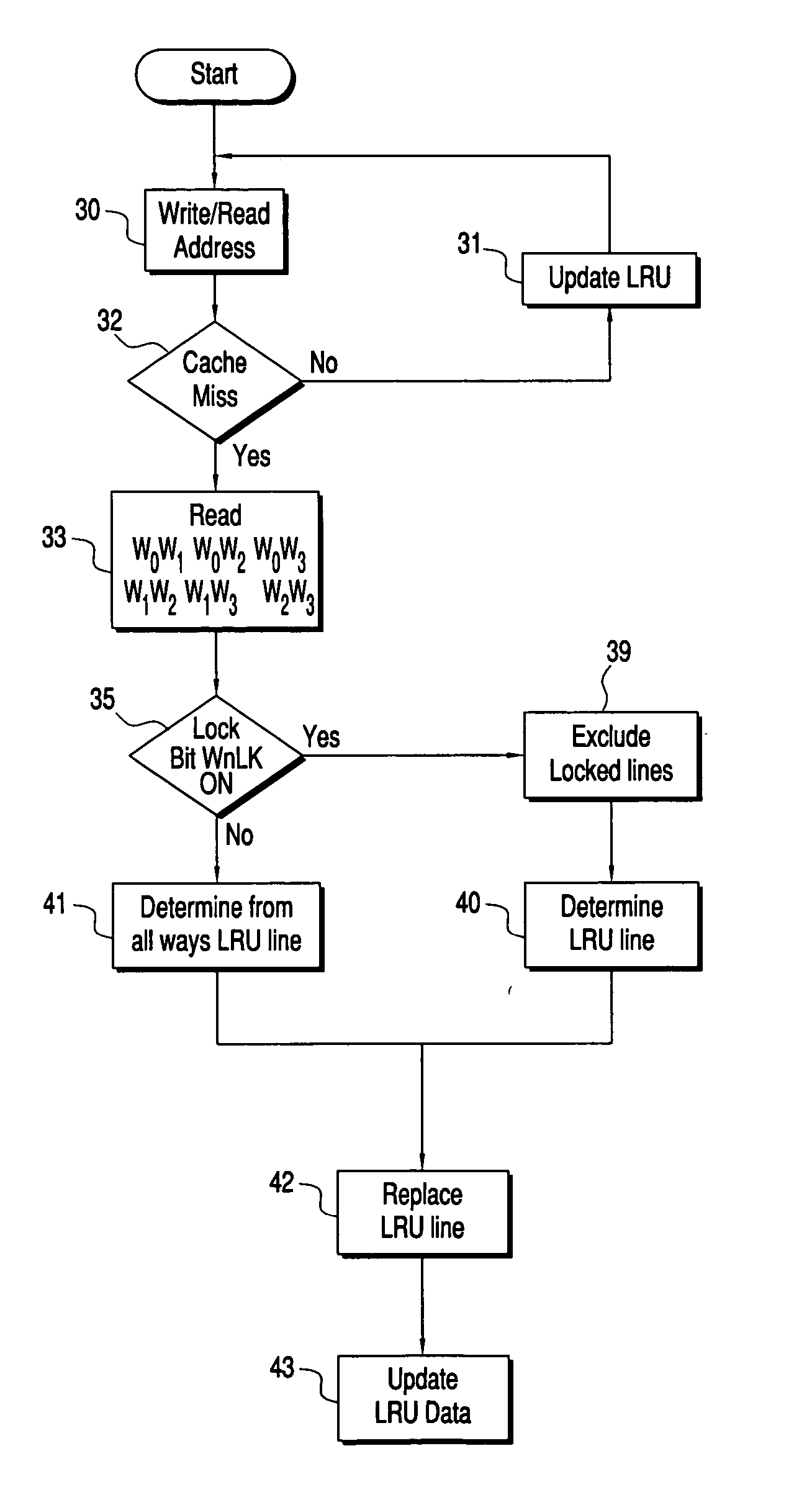
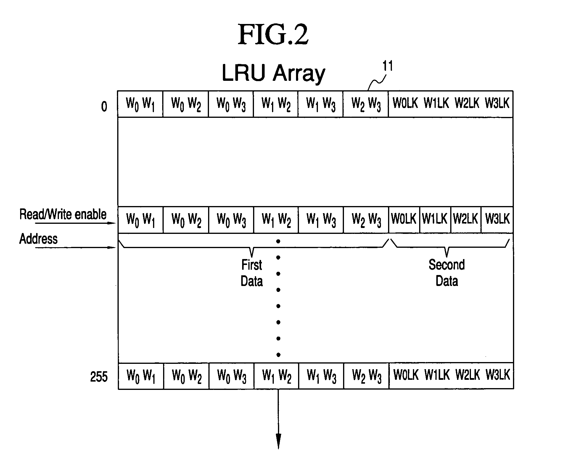
An LRU array and method for tracking the accessing of lines of an associative cache. The most recently accessed lines of the cache are identified in the table, and cache lines can be blocked from being replaced. The LRU array contains a data array having a row of data representing each line of the associative cache, having a common address portion. A first set of data for the cache line identifies the relative age of the cache line for each way with respect to every other way. A second set of data identifies whether a line of one of the ways is not to be replaced. For cache line replacement, the cache controller will select the least recently accessed line using contents of the LRU array, considering the value of the first set of data, as well as the value of the second set of data indicating whether or not a way is locked. Updates to the LRU occur after each pre-fetch or fetch of a line or when it replaces another line in the cache memory.

Description

[0001] The present invention relates to computer processor memory caches such as a set associative cache. Specifically, a cache memory and method for controlling the cache memory is provided so that line replacement may be selectively controlled. [0002] Computer processors use cache memories to reduce the access time for instructions as well as other data. Computer systems having a main memory containing all necessary instructions for executing an application suffer from execution delays because of the time needed to recover a necessary instruction from the mass memory. Accordingly, a cache memory is provided which permits the processor during a pre-fetch process to move instructions from the main memory to the cache memory where they may later be accessed when needed. [0003] Even though cache memories speed up the access time for retrieving instructions, there still exists a disparity between the computer processor operational frequency and the access time for data to be stored in ...

Claims


Application Information

Patent Timeline
IPC IPC(8): G06F12/00
CPCG06F12/126G06F12/125
Inventor DIEFFENDERFER, JAMES N.DOING, RICHARD W.FRANKEL, BRIAN E.TSUCHIYA, KENICHI
Owner GOOGLE LLC
Learn More